
This is the configuration that is being used as of the date of this writing on April 25, 2007
If you are planning on building a Rife/Bare system, please be sure to read my NOTES at the end of this article.
For an overall view of my unit, you can jump to the System Specifications.
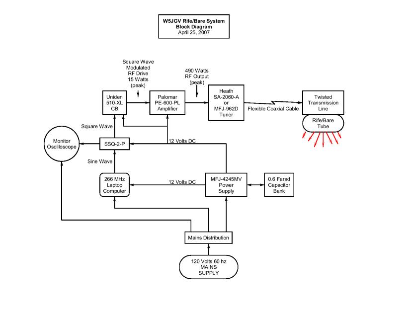
You can jump to a block diagram of my system.
After much testing and experimentation, I decided it would be nice to have a "finished" Rife/Bare system that did not fill up a whole rack cabinet. Since we had just moved to a new home and I had to disassemble everything in my old rack mounted Rife/Bare system, I decided to reassemble the system in a much smaller space. Since I had pretty much worked out what I would need to make it all work, I finally came up with the unit you see in the pictures below.
The entire system, except for the lampholder and Rife/Bare tube, is installed in a wheeled wire frame cart, that measures 18" x 18" x 36" or 46 cm x 46 cm x 91.4 cm. Since it is on wheels, it may be conveniently moved out of the way when not in use. A single power cord connects to the mains, and a single coaxial cable connects the unit to the lampholder assembly.
The laptop computer on the top of the rack generates the audio sine wave that is used to produce the square wave Rife frequencies for the modulator. Below the laptop computer is a small oscilloscope which is used to monitor the square wave that modulates the transmitter. Directly under the oscilloscope is Heath SA-2060A antenna tuner that matches the amplifier to the Rife/Bare tube system. On the bottom shelf is the Palomar PE-600-PL RF amplifier, which is on top of the MFJ-4145 MV power supply. To the right of the power supply is a bank of filter capacitors. To the right of the capacitors is the Uniden PRO-510-XL CB transmitter. Above the CB is the SSQ-2-P sine wave to square wave converter.

A rear view of the Rife/Bare electronics unit. A power distribution strip is attached to the lower frame of the cart so the mains power can be fed to the units requiring it. The heavy coaxial cable can be seen connected between the output of the RF power amplifier and the input of the antenna tuner. The coaxial cable that connects to the lampholder is connected to one of the open connectors on the bright copper colored panel on the rear of the antenna tuner.

On the bottom shelf is the power supply, which is connected by the heavy red and black wires to the large blue filter capacitors. To the right of the capacitors is the CB transmitter, which is mounted on its side. On top of the CB is the SSQ-2-P. On top of the power supply you can see the Palomar RF power amplifier.

A view of the right side of the rack shows the bottom of the CB transmitter. you can see the small cooling fan that was added to the CB when I modified the unit in order to boost the output power from 4 watts to 20 watts. On the top of the blue filter capacitors is a dual outlet 12 volt DC power socket for accessories. Note the red and black binding post connectors on the front side of the Palomar amplifier. Connected to these terminals is a large cooling fan that was added to the top of the amplifier to help cool it. Another fan was added beneath the amplifier to aid in cooling the components inside the amplifier.

A rear view of the lower shelf on the rack. You can see the power distribution strip, the back of the power supply, the back of the Palomar amplifier, and the filter capacitors. The extra length of the DC power cables to the amplifier are coiled up behind the power supply.

There are four large capacitors connected in parallel. They are connected together with solid copper strap measuring 12 mm in width by 1.5 mm thickness. The value of each capacitor is 150,000 uF at 15 Volts DC. This gives a combined filter value of 0.6 Farads. It was necessary to add a "soft start" circuit to allow the capacitors to slowly charge up when the power supply is first turned on, or else the initial inrush current when the capacitors start to charge from the power supply would cause the power supply to shut down immediately. The large rectangular white resistor and the square black relay that make up the soft start circuit may be seen on top of the last capacitor (the one closest to the front of the rack.)

Here is a front view of the filter capacitors and the soft start relay. The two blue indicator lights show the charging status. The "CHG" (Charge) light illuminates during the initial charge process, then it goes out and the "RDY" (ready) light comes in as the relay closes its contacts and connects the capacitor bank directly across the power supply output connections. The capacitor bank is required due to the heavy pulse current drawn by the RF amplifier. This pulse current will cause the power supply to shut down when it should not do so.
>>> PLEASE SEE NOTES AT END OF ARTICLE<<<

Here you can see the heavy coaxial cable that connects the output of the RF amplifier to the tuner. The thin black coaxial cable connects the output of the CB transmitter to the input of the RF amplifier. The black coiled cables are the DC power leads that feed power to the RF amplifier. They are made from #2 AWG welding cable. They are longer than is necessary because I once used the amplifier in another system where the long leads were required. Since the extra length does not cause a problem in this application, I simply coiled up the excess cable instead of cutting them shorter. Notice the small black ferrite RF filter choke that has been fitted over the DC power wires where the power wires enter the amplifier. This filter was necessary to eliminate stray RF leakage and radiation from the amplifier through the power leads.
The amplifier is raised from the top of the power supply by using two strips of wood. This is to allow a fan which is installed under the amplifier to blow cooling air through the components on the under chassis of the amplifier.
RF amplifiers which were designed for CB radio service do not have enough cooling for continuous duty when they are used in Rife/Bare service. Additional cooling MUST be added, both on the top of the heat sink, and to the inside of the amplifier. Failure to keep the heat sink cool enough will cause the RF power transistors to burn out. It is a good idea to make sure that the manufacturer used a sufficient quantity of heat sink thermal compound between the case of the transistors and the heat sink. It may be necessary to use an infrared thermometer to ensure that the case of the transistor does not exceed the manufacturers specifications when the amplifier is in operation.
In addition to cooling the heat sink, if the inside of the amplifier is not also well cooled, components and circuitry may become hot enough to fail. Sometimes the circuit board becomes hot enough to melt the solder and components mounted on the circuit board will fall off, rendering the amplifier useless. I cut a hole in the bottom of the RF power amplifier case and installed a small fan to blow air inside the amplifier. I cut another hole to allow the heated air to exit from the case.
>>> PLEASE SEE NOTES AT END OF ARTICLE<<<

You can see the large fan that I added to cool the heat sink of the amplifier. Mounted under the amplifier is another cooling fan. It sucks cool air between the amplifier and the top of the power supply, then blows it into the lower front of the amplifier case. Another hole is cut in the bottom of the amplifier case near the rear of the case. Hot air exits the amplifier through this hole. A strip of wood is placed cross-ways between the two strips of wood that support the RF amplifier. This forms an "H" between the two wood strips supporting the amplifier over the power supply. This cross-ways strip prevents the hot air from flowing back to the fan and being blown back into the amplifier. The "finger guards" for the fans are easily made from some readily available wire mesh and attached to the fan by using four plastic cable ties.

Another view of the two cooling fans on the amplifier. It looks as though I should clean off some dust! The fans keep the amplifier heat sink cool so that it becomes just slightly warm to the touch. If your amplifier heat sink becomes so hot that it is uncomfortable to keep your hand on it continuously, it is too hot for the amplifier to work safely. Add more cooling!

The monitor oscilloscope and antenna tuner. The coiled white cable in the rear basket is used to connect the antenna tuner to the Rife/Bare lampholder.

A nice looking square wave! The system is working nicely. This oscilloscope monitors the output of the SSQ-2-P waveform converter.

The meters on the antenna tuner show that the system is sending an average power level of 170 watts to the Rife/Bare tube. This is a peak power level of close to 340 watts, since the signal is a square wave, and not a continuous signal. The actual power available to the Rife/Bare tube will be somewhat less, due to the losses in the coaxial cable and the Twisted Transmission Line used in the lampholder. The reflected power is less than 1/4 watt, so most of the power is being sent to the Rife/Bare tube.
>>> PLEASE SEE NOTES AT END OF ARTICLE<<<

In this picture, you can see the small cooling fan on the bottom of the RF power amplifier - it's just above the top of the power supply. The power supply meters indicate about 30 Amperes at 13.8 Volts, or a load of about 400 watts.
>>> PLEASE SEE NOTES AT END OF ARTICLE<<<

This is the screen that is displayed on the laptop computer when the computer is controlling the Rife/Bare system. I use Fred Walter's FREQGEN program to generate the frequencies during a session. I have the screen set to display a red background to warn me to check carefully before changing anything during a session.

A side view of the computer shelf shows the network cable attachment box and the storage rack for the coaxial cable and documentation papers.

A rear view. Note the simple aluminum brace that holds the laptop computer screen at the correct angle for use. The screen hinges have worn out, and the top will not stay adjusted in place without the support brace.

This is the lampholder for the Rife/Bare tube in my system. It is shown here with the support tube fully retracted. The base and tube support is a standard microphone stand used in radio studios. The white lamp housing is made from a 1,000 watt outdoor flood light fixture. I removed the original parts inside the fixture and painted the interior a glossy white. I did not use the glass that was in the fixture, because the glass will absorb some of the light from the Rife/Bare tube when in operation. The metal mesh screen covering the front of the fixture was installed to prevent unnecessary RF radiation during operation. The outer ends (which contain the internal tube electrodes) of the Rife/Bare tube protrude through the sides of the lamp housing. I covered the lamp ends with more of the metal screen which I formed into a box-like shape. These covers serve to both prevent RF radiation and to protect the fragile glass tube ends from damage. On top of the lamp housing is the Twisted Transmission Line in its black case.

This is the lampholder for the Rife/Bare tube in my system. In this photo it is shown with the support tube fully extended.

A rear view of the lamp holder. You can see the protective screens that are placed over the ends of the Rife/Bare tube and the Twisted Transmission Line enclosure.

Front view of the lamp holder. The copper collars on the tube are the external electrodes to which the RF power from the amplifier is applied. In this unit, the internal electrodes of the Rife/Bare tube are not used.

One of the tube end shields. The lamp housing is cast aluminum, so I was able to drill and tap the holes for the mounting screws. The all metal construction provides excellent RF shielding, as well as providing protection for the tube electrode ends from accidental damage.

In this photo the RF shield has been removed. You can see the red terminals where the RF power from the Twisted Transmission Line enters the lamp housing. The copper wires send the RF power to the two copper collars on the Rife/Bare tube. The copper collars act as capacitor plates. When the voltage on the collars becomes high enough, the gas inside the tube closest to the collars ionizes, and the tube quickly lights up.

The copper collar electrodes are easily fabricated from a flat strip of thin copper which is carefully formed to fit around the tube. Short tabs are formed in the copper at the open ends of the collar. A hole is drilled through each tab so that a bolt may pass through the two tabs. The collar does not quite encircle the tube completely, so that when the nut is tightened on the bolt that clamps the collar against the tube, the spring action of the copper tabs on the collar keeps the collar pressed tightly against the tube wall. The spring action of the copper allows it to expand and contract with the tube as it heats and cools so there is little chance of breaking the tube in normal operation. The tube is made of such a length that the neck of the tube ends passes through the circular holes cut in the opposite ends of the lamp housing. The tube is cushioned by several lengths of split rubber tube which are fitted over the edges of the holes. The rubber allows for the lengthways expansion of the tube during operation.

The Twisted Transmission Line in its case is mounted to the top of the lamp holder.

A close-up view of the Twisted Transmission Line. The metal mesh screen allows cooling air to get in to cool the line while at the same time preventing unwanted RF radiation from the line.

Here is the Rife/Bare tube shown while running at about 300 watts peak RF power. Note that the strongest glow is between the copper collar electrodes. The fringing RF field from the electrodes causes the section of tube between the electrodes and the ends of the lamp holder enclosure to light up, but not as brightly.

This shows the intense glow inside the tube close to the tube wall beneath the copper collar electrode.

Another view of the tube in operation. This Rife/Bare tube has a gas mixture composed of 10% Neon and 90% Argon. The visible color changes slightly, depending on the applied RF power level, becoming more violet in color as the applied RF power increases. The active area of the tube between the copper collar electrodes is about 35.6 cm in length by 5.1 cm in diameter. The tube is about 50.8 cm overall including the interior electrodes. The copper collar electrodes are spaced about 21 cm apart on the tube. The tube was designed to operate with a minimum power level of 100 watts peak, and a maximum power level of 700 watts peak. Forced air cooling is not required at power levels below 400 watts. The tube was custom manufactured for me by Robert Randazzo.

The tube operating inside the RF screen. Note the even glow throughout the tube.

This is the complete system with the coaxial cable connected to the lampholder and the antenna tuner. The coax cable is coax cable is 436.88 cm in length (14 feet 4 inches) with a Velocity of Propagation of 0.80. This length allows easy tuning of the system and is long enough for convenience in placing the lampholder where it is needed during the session. Cables of up to 14.4 meters (50 feet) have been used, but the power available to the Rife Bare tube is reduced by about 75 watts due to the losses in the cable.

Ready to go!

A time exposure - the system providing the light to take its own picture.
After a LOT of designing, building, experimenting and tearing things apart and putting them back together again, I have found a few traps for the unwary experimenter, particularly if you are not experienced with electronics. I'm going to mention some of them here. Hopefully these comments will assist you in building a better, more reliable system.
The first big problem many experimenters encounter is that their RF power amplifiers burn out when used for long periods of time. This is not surprising, because most RF power amplifiers which were designed for CB radio service do not have enough cooling for continuous duty when they are used in Rife/Bare service.
Additional cooling MUST be added, both on the top of the heat sink, and to the inside of the amplifier. Failure to keep the heat sink cool enough will cause the RF power transistors to burn out. An additional fan (or two) should be added to make sure that plenty of cooling air flows over the heat sink. When mounting the fan, make sure you do not position the fan so that there are any "dead air" areas on the heat sink. This may happen if the fan is too close to the heat sink or you have two fans that happen to be blowing air against each other.
It is also a good idea to make sure that when the amplifier was assembled at the factory, the manufacturer used a the correct amount of heat sink thermal compound between the case of the transistors and the heat sink. It may be necessary to use an infrared thermometer to ensure that the case of the transistor does not exceed the manufacturers specifications when the amplifier is in operation. If there is not sufficiently effective heat conductivity between the transistor and the heat sink, the transistor may burn out even though the heat sink remains cool to the touch.
In addition to cooling the heat sink, if the inside of the amplifier is not also well cooled, components and circuitry may become hot enough to fail. Sometimes the circuit board becomes hot enough to melt the solder and components mounted on the circuit board will fall off, rendering the amplifier useless. In my particular amplifier, I cut a hole in the bottom of the RF power amplifier case and installed a small fan to blow air inside the amplifier. I then cut another hole to allow the heated air to exit from the case.
But why should the amplifier get so hot? The answer is in the way you are going to use the amplifier. In normal CB service, the amplifier is expected to produce maximum power output only on the loudest peaks of the voice signal. This is usually considered to operate the amplifier at about one-third (1/3) of the power rating of the amplifier. In the case of my PE-600-PL, the rating is 600 watts peak for 1/3 of the time, or an average of only 200 watts. And that is only intermittently, since the operator does not talk all the time. The operator will often pause during conversation, turn off the transmitter to listen to the other station he's talking to. This allows the amplifier adequate time to cool down. The actual average power that the amplifier is called on to produce is probably closer 100 watts.
However, if I try to drive the amplifier to the full 600 watts on peaks, which will happen when I drive it with a square wave audio signal in Rife/Bare service, I am now trying to force the amplifier to produce an average power of 300 watts. This is half of the 600 watt peak power level, since the square wave is off 50% of the time. This 300 watt average power level will quickly cause the amplifier to overheat and fail unless additional cooling is added.
To make the problem even worse, it is a known fact that the losses in a transistor increase as the transistor becomes hotter. So, when the amplifier gets hot, more power is dissipated inside the transistor, which makes it get hotter, which makes it dissipate more power, and this continues in a downward spiral until you have a thermal runaway condition, which quickly leads to destruction of the power transistors. Then answer - KEEP IT COOL!
Another cause of amplifier failure is excessive heat caused by incorrect bias on the amplifier transistors. CB amplifiers as furnished from the manufacturers generally are electrically biased for operation in Class "AB" or Class "B" mode. This is done to provide some linearity in the amplification of the RF signal from the low powered CB transmitter. However, in Rife/Bare service, we want the amplifier to be biased into Class "C" service. Adjusting the bias to Class "C" will reduce the power transistor heating, at the expense of amplification linearity. However, we do not want a linear amplifier.
What we want is an amplifier that will operate like a big "ON/OFF" switch. We want it to produce full power when we turn it ON with the positive part of the square wave modulating signal, and to produce no power when we turn it OFF with the negative part of the square wave modulating signal. Class "C" operation works in that way. The one thing that will change with Class "C" operation is that the drive signal to the amplifier will need to be greater because Class "C" operation requires a larger drive signal for technical reasons. You may need to modify your CB transmitter slightly or add a small amplifier between your CB and your main RF power amplifier.
It is important that the RF amplifier be driven by the CB as "hard" as possible (Increase the RF driving power from the CB to the RF amplifier), particularly if it is not possible to adjust the amplifier for Class "C" operation. Driving the RF amplifier "hard" will drive the RF amplifier transistors as far into saturation as possible, and raise the efficiency of the RF amplifier. This will produce more RF output from the amplifier, and also reduce the losses in the output transistors, helping them to run cooler.
It is VERY IMPORTANT that the manufacturers' maximum ratings for the power transistors in your RF amplifier not be exceeded, or you run the risk of damaging or destroying your transistors. It is important to realize that when driving your RF amplifier with the CB that is modulated by a square wave, that the current reading displayed on the power supply ammeter is the AVERAGE current through the transistors. The PEAK current is TWICE the average current reading. You must be careful not to exceed either the average current or the peak current ratings of your transistors as defined by the transistor manufacturer.
A high power RF amplifier in Rife/Bare service presents a difficult load to the DC power supply. Because we are requiring the amplifier to produce high power square wave RF pulses, this will cause the RF amplifier to try to draw a square wave of DC power from the power supply. In effect, the amplifier load is being switched on and off the power supply terminals at the frequency of the square wave. Many power supplies do not like this type of load, and will simply shut down and quit producing any power.
In the case of my system, the supply would shut off when the ammeter read a load current of only 22.5 Amperes instead of the 45 Amperes the supply was rated for. What was happening? Some quick calculations told me that when the meter reads 22.5 Amperes, the PEAK load was actually 45 Amperes, because the square wave is off half the time, so the meter was reading only half of the peak current the power supply was having to supply to the amplifier. That is why I had to add the large blue filter capacitors shown in the photos of my system.
Inside every RF power amplifier are one or more electrolytic capacitors which are connected across the power supply wires. The function of these capacitors is to act as "bypass" capacitors to filter out the human voice component of the current drawn from the power supply. The capacitors also help to keep the DC power at the amplifier constant as the drive to the amplifier changes during modulation. Because of their function, these capacitors will have a large AC current flowing through them during modulation of the drive signal. This is an intermittent condition with voice (CB) operation, but is continuous during Rife/Bare operation.
This current is equal to the DC current drawn by the amplifier, and the frequency of the current is at the modulation frequency. As a result of this AC current flowing through the capacitors, they get hot when the amplifier is driven by a square wave. In fact, in some cases, the capacitors will become so hot that they literally explode!
This happened several times while testing my PE-600-PL amplifier. The solution was to install several additional capacitors, but of a higher temperature and lower loss rating than the original capacitors. As delivered from the manufacturer, my amplifier had two capacitors, each rated at 90 degrees C and 470 uF at 15 Volts. I replaced those two capacitors with a total of 6 new capacitors, each with a rating of 105 degrees C and 1500 uF at 15 Volts. This cured the exploding capacitor problem. The new capacitors also increased the power output the amplifier by almost 50 watts.
Some quick facts for your calculations:
- The RF amplifier is only about 50% efficient in converting DC power into RF power.
- The power supply ammeter will read the AVERAGE current drawn by the RF amplifier.
- The PEAK current drawn by the RF amplifier is twice the reading on the power supply ammeter.
- The AVERAGE DC power drawn by the RF amplifier is: Volts x Amps.
- The PEAK DC power drawn by the RF amplifier is: (volts x amps) x 2
- The AVERAGE RF power from the RF amplifier is: (Volts x Amps) / 2
- The PEAK RF power from the RF amplifier is: (Volts x Amps)
For example, my amplifier at absolute full power draws 35 Amperes at 14 Volts
so:
DC AVERAGE power = 35A x 14V = 490 Watts
DC PEAK power = (35A x 14V) x 2 = 980 Watts
RF AVERAGE power = (35A x 14V) / 2 = 245 Watts
RF PEAK power = 35A x 14V = 490 Watts
My amplifier has been modified for Class "C" operation. In CB service, it was rated at an RF output of 250 watts peak, and 85 watts average power. As you can see, I have "pushed" the amplifier to a much higher power level than it was designed for by the use of Class "C" operation and LOTS of extra cooling
System Type - Rife/Bare RF Excited Gas Tube with square wave modulation
RF Excitation Frequency - 27.120 MHz
Power Amplifier - Palomar PE-600-PL (modified for Class "C" operation and with additional cooling)
Normal RF Operating Power Output - 245 watts (avg), 490 watts (peak)
RF Driver - Uniden 510-XL (old type) modified for 20 Watts peak output
Modulation type - Square Wave Modulation
Frequency Source - Laptop Computer soundcard output
Software - FREQGEN sinewave generator
Waveform Converter - SSQ-2-P Sine to Square Wave Converter
Main Power Supply - MFJ-4245MV switching supply, 24V @ 45 A
RF Tuner - Heath SA-2060A (or MFJ-962D)
Interconnecting Cable - Foam filled RG-8 type coaxial cable
RF Match to tube - Twisted Transmission Line system
Rife/Bare Tube - Robert Randazzo (Absolutely Neon) special manufacture item. The active area of the tube is about 35.6 cm in length by 5.1cm in diameter. The tube is about 50.8 cm overall including the interior electrodes
[ Home ]
This page and all text, data and photographs is Copyright © 2007 by Ralph M. Hartwell II, All Rights Reserved.