By Tom Young
This is a modification to the Uniden Pro510XL CB radio which
replaces Jim Bare's original audio modulation method with a direct RF
modulation method. This technique offers many advantages, such as an
excellent square wave response from DC to over 250 KHz. Also, the pulse
width, or duty cycle, is precisely controllable assuming that you are using a
function generator that has this capability. The only disadvantage is a
peak output power reduction from 16 watts to 4 watts, but a 24-volt power
supply can be added to the system to bring the peak power levels up to about
20-22 watts (instructions at bottom of this page).
The circuit is very simple (only 4 parts) and costs next to nothing ($3 or less). If you are not at all handy with a soldering gun, though, you might want to seek the help of someone who is. Please see the related pictures for a good view of parts placement.
Parts required:
Step 1: Remove the top and bottom covers.
Step 2: Remove the internal speaker from the bottom cover (4 screws/nuts) and cut its wires close to the circuit board. We have no need of it and it takes up valuable space.
Step 3: Place the radio upside-down with the front facing you. For all descriptions to follow, left is your left, right is your right. Whenever I say "from the left/right/rear edge", I mean from the edge of the radio's metal chassis. For clarity, I have capitalized the functional name of the component leads. Good luck!
Step 4: Find the 27-ohm 5% resistor (red-violet-black-gold) which is located 42mm (1 5/8") from the rear edge and 14mm (9/16") from the left edge. It is lying flat on the board. Cut the resistor's right-side lead as flush with the board as you can (or desolder it from the bottom), then lift the resistor up on its left lead at a 45-degree angle.
Step 5: Find the metal RF transformer labeled L2. It is 56mm (2 3/16") from the rear edge and 33mm (1 5/16") from the left edge. Using your solder gun, heat the top side front-left corner of L2's shield and place a bead of solder there.
Step 6: Spread the leads of the 2N3904 so Emitter and Collector point away at 45-degree angles. Hold the 2N3904 horizontal in your left hand with the flat side (printed side) facing up and the leads facing to the right. Solder the Emitter lead of the 2N3904 to L2's solder bead that you just made.
Step 7: Stretch the 2N3904 Collector lead over to the free-floating 27-ohm resistor lead and solder them together.
Step 8: Cut both leads of the 1N4148 diode to a length of about 1/4". Solder the Anode of the diode to the solder bead on L2 and solder the Cathode (band end) to the Base lead of the 2N3904.
Step 9: Cut both leads of our 10K resistor (or 3.3K or whatever size you picked) to about 1/4". Solder one lead to the Base lead of the 2N3904. Solder a 6" length of 20 or 22 gauge stranded hookup wire to the other side of the 10K resistor. If you have some, slip 2 or 3 ferrite beads over this wire to prevent RF from feeding back into the circuit.
Step 10: Remove the audio output transformer. It is located 30mm (1 3/16") from the rear edge and 48mm (1 7/8") from the right edge. It is labeled "TF-375". I recommend using desoldering braid to do this (Radio Shack #64-2090). You must desolder all 5 leads plus the two metal tabs that extend from the metal frame.
Step 11: Construct a jumper wire of 18 to 22 gauge solid wire and make it 18mm (11/16") between the bends. Again, place the radio upside-down facing you. Insert one side of the jumper wire into the left-rear transformer hole and the other side into the middle hole of the 3 front transformer holes. Solder the jumper wire in place.
Step 12: Position the 470uF capacitor inside the radio where the audio transformer used to be. Solder the positive lead of the capacitor to the jumper wire you just installed, and push the negative lead through one of the transformer holes where the metal tabs were. Solder the negative lead to the ground foil on the bottom side.
Step 13: Flip the radio right-side up, facing you. Notice the 4 philips-head screws holding the circuit board to the chassis. Look closely at the 2 screws on the right side. There is copper foil completely around these screws and also a gap and more foil to the rear of both screws. Using a small flat-tip screwdriver or wood chisel, scrape away the coating on the copper foil to the rear of both screws and on both sides of the gap. Solder a short straight jumper wire across each gap. Do it for both screws. This modification connects the circuit common to the actual chassis, which provides better grounding for the audio generator and can prevent certain types of feedback.
Step 14: (Optional) This is a component replacement that
provides for slightly sharper square waves when modulating above 200 KHz.
Find the .01uF ceramic disc capacitor just behind the 27-ohm resistor we've
been
working with. It's about 7mm diameter and labeled
"103M". Desolder and replace this with a 470pF disc
capacitor. This reduces the square wave rise/fall time from 125nS to
about 50nS.
Step 15: Re-assemble the radio. When placing the bottom
cover, run the 6" piece of hookup wire through one of the holes of the speaker
grill. Connect your audio/function generator to this wire and chassis
ground.
That's it! Incidentally, the reason for yanking the audio
output transformer and installing the 470uF is to smooth out RF envelope
fluctuations that would occur below about 200 Hz. You can now enjoy
experimenting with modulation frequencies all the way from DC to almost 1
MHz.
Two things to check if you perform the mod and find that you have no RF output from the radio...
1. Make sure your generator is putting out at least +1.5V peak (above ground) voltage or it may not activate the 2N3904 transistor. If you don't quite have that much drive, reduce the 10K resistor to a 1K, and that should do it.
2. Put a voltmeter on the collector of the RF output transistor
2SC2166 and make sure 12V is getting to it -- if not, check the jumper that you
installed where the transformer was, as it must now connect the 12V to the
transistor or you'll get no RF output. Before the mod, the output
transistor was getting its 12V through the secondary winding of the audio
transformer.
To incorporate a 24-volt external power supply into the system and bring the peak power level up to about 20-22 watts, just replace steps 11 and 12 in my original instructions with the following...
Step 11: Cut a 6-inch length of 16- or 18-gauge stranded hookup wire. Again, place the radio upside-down facing you. Insert one side of the hookup wire into the left-rear transformer hole and solder it in place. Run the wire through any convenient route out the rear of the radio (I drilled a 1/8" hole next to the antenna jack). Connect the positive lead of a 24-Volt 1.5-Amp (or better) regulated power supply to this wire. Connect the 24-volt supply's negative lead to chassis ground.
Step 12: Position the 470uF capacitor inside the radio where the audio transformer used to be. Solder the positive lead of the capacitor to the cathode lead (banded end) of diode D7, which is located immediately to the left and rear of where the audio transformer was. Push the negative lead of the capacitor through one of the transformer holes where the metal tabs were. Solder this lead to the ground foil on the bottom side.
With the CB in transmit and the generator applying a signal to the 2N3904 circuit, peak the coils L6 and L9 for maximum output, using a wattmeter or oscilloscope. You should obtain a peak power of about 20 to 22 watts (will read about 10 watts on an average-reading watt meter with 50% generator duty cycle).
Click HERE to see photos of the modification process
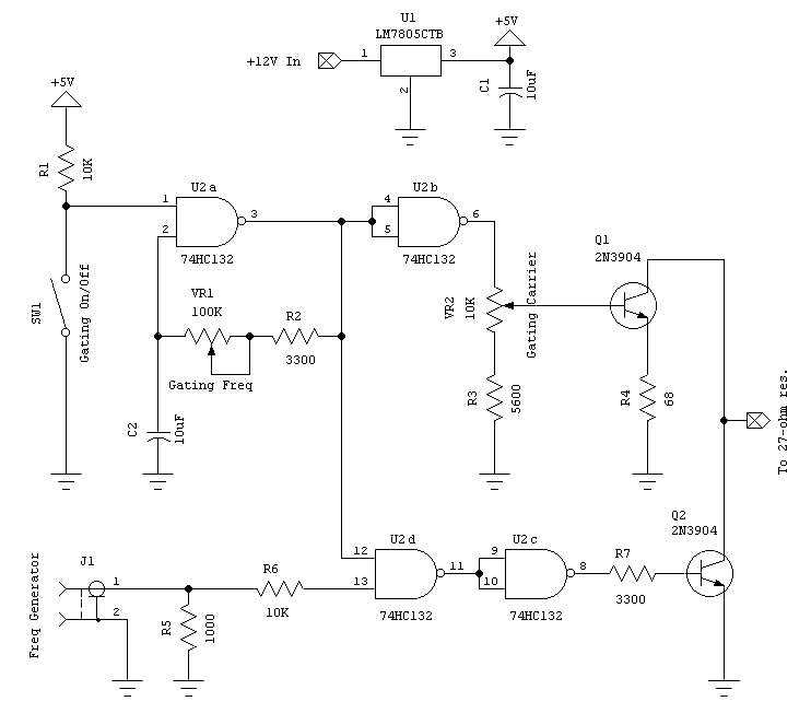
Click HERE for a schematic of the modification. (Right-Click to download.)
[ Home |