
February 19, 2010 - By W5JGV
This article describes a simple but effective receiving antenna that covers a wide range of frequencies. It requires an amplifier which serves the dual function of amplifying the received signals and matching the high impedance of the short vertical antenna to the transmission line that connects the antenna to the various receivers inside the shack.
The W5JGV E-probe antenna as installed in Natchitoches, Louisiana, USA.
The antenna consists of a 9 foot (2.75 Meter) length of #10 AWG copper wire. The wire is enclosed in the gray PVC pipe. The wire need not be insulated. The top and bottom ends of the PVC pipe are capped with glued on slip on pipe caps which ensure that water does not get into the antenna.
The amplifier for the antenna is inside the translucent plastic box seen mounted on the wooden support pole. The amplifier is the same amplifier which was used with my Tree-Tenna. The amplifier is powered by DC over the coax from the shack. Please click HERE for information about the amplifier.
An 8 foot (2.45 Meter) copper-clad ground rod is driven into the earth at the base of the support pole. The coaxial cable between the amplifier and the ham shack is RG-6 TV coaxial cable. The amplifier and the shield of the coaxial cable from the ham shack are both connected together and connected to the ground rod. For ease in troubleshooting, the coaxial cable is spliced and fed through a standard TV cable grounding block. The ground block is located under the translucent blue plastic rain shield mounted on the support pole beneath the amplifier.
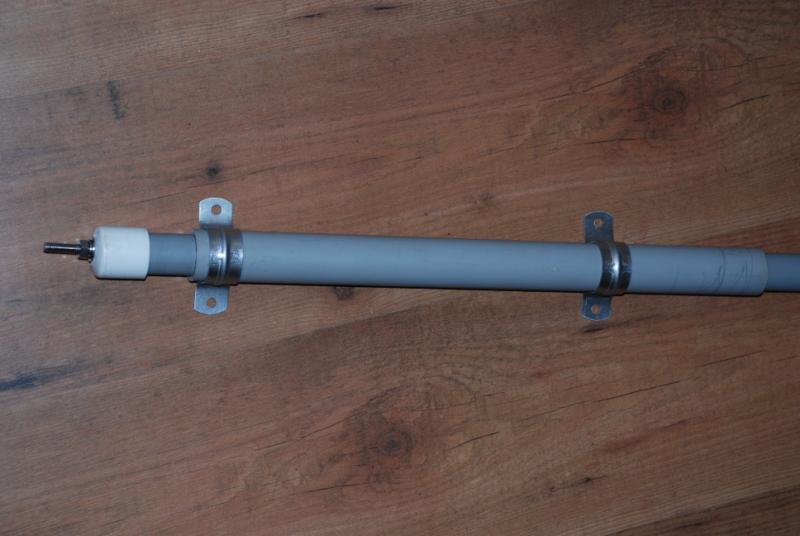
To prevent the PVC pipe from bending and breaking under wind stress, the lower end of the pipe was reinforced by slipping a length of the next larger PVC pipe over the antenna pipe. Standard pipe mounting "U" straps were then used to attach the antenna pipe to the mounting pole.
The bolt seen protruding through the white pipe cap is connected inside the PVC pipe to the lower end of the #10 gauge copper antenna wire. Stainless steel nuts hardware was used for this connection to prevent corrosion.

Because you cannot easily slip the PVC antenna pipe into the reinforcing section of PVC pipe, it was necessary to cut the larger reinforcing pipe lengthways along one side only. That allowed enough flexibility in the reinforcing pipe to be able to force the smaller pipe into the larger. It was a tight fit!
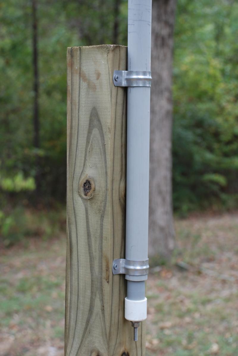
The antenna pipe as mounted on the weather treated 4X4 wooden support post.

Even though E-Probe antennas are not supposed to work well when located close to trees, as you can see, the antenna is located amongst a grove of large trees. Nevertheless, the antenna performs admirably.

The W5JGV E-Probe antenna before the amplifier and coaxial cable were installed.

The W5JGV E-Probe antenna ready for use.
The amplifier is seen inside its protective enclosure, and the aluminum wire connecting the antenna to the amplifier is just visible to the left of the amplifier. The ground block and coaxial cable termination point is under the blue rain shield. The top of the ground rod is visible just in front of the wooden support post. A few extra turns of coax cable were left coiled around the base of the antenna just in case something happened to the cable, such as a lawnmower accident, or a squirrel or raccoon gnawing on the cable.

The amplifier is enclosed in a metal electrical box and then placed inside the plastic enclosure. (Note to self: Use a better quality plastic box the next time! This box deteriorated in two years time, and the hinge broke, allowing the cover of the enclosure to flop open.)
Note that the bare aluminum wire from the bottom of the antenna is just stuck into the center connection of the "F" connector on the input of the amplifier. Because the amplifier's input has a very high impedance, coaxial cable should not be used to connect the antenna to the amplifier.
The UHF to BNC adapter seen here is used for connecting a portable receiver to the output of the amplifier for field tests, and is otherwise not used. The coaxial cable connecting to the second "F" connector behind the UHF/BNC adapter is the RF output/DC input of the amplifier.

The connecting wire between the bottom of the antenna and the amplifier input.

The antenna is almost invisible amongst the trees in this photo. The antenna's location is about 200 feet (61.2 Meters) away from the ham shack and slightly downhill from the ham shack. The coax cable from the antenna to the ham shack is simply laid on the ground and left there. RG-6 is cheap, so if it gets damaged, it is simple to replace it. The cable runs from the antenna up the hill to the left and then on to the ham shack.

Looking up the hill towards the ham shack, you can see the cable laying on the ground. I used the lawn mower and cut the grass and weeds very close to the ground so the cable was pretty much laying on the bare earth. After a year, the cable has become invisible under the new grass.

The cable makes a bend or two as it gets closer to the shack. The bends are "pinned" to the earth by using short lengths of metal tube bent into a "J" shape.

The cable runs along the ham shack foundation until it reaches the cable entry box on the wall of the shack.

Here the cable turns up and enters the shack through a length of PVC conduit and through the cable entry box. There is a grounding plate through which all of the antenna cables pass to and from the shack.
73,
Ralph - W5JGV - WD2XSH/7
[BACK]
All Pages, photographs, text or other data in any form on this Web Site are Copyright © 2001-2010 by Ralph M. Hartwell II or their respective authors.