Sept 17, 2007 - By W5JGV
When I needed an effective RF preamplifier for my Tree Antenna I wanted a low-noise unit, with lots of gain. It needed to be able to cover frequencies from a hundred KHz or so up to about 30 MHz. I also wanted to be able to power it over the coax cable connecting it to the receiver. I thought about doing a ground-up design for the amplifier, but, instead, I did what every good engineer does when confronted with a similar design problem - I swiped the design from someone else. After all, why re-invent the wheel?
A search of my computer files quickly located a nice looking amplifier designed by Philip Atchley, KO6BB. The original circuit is located HERE.

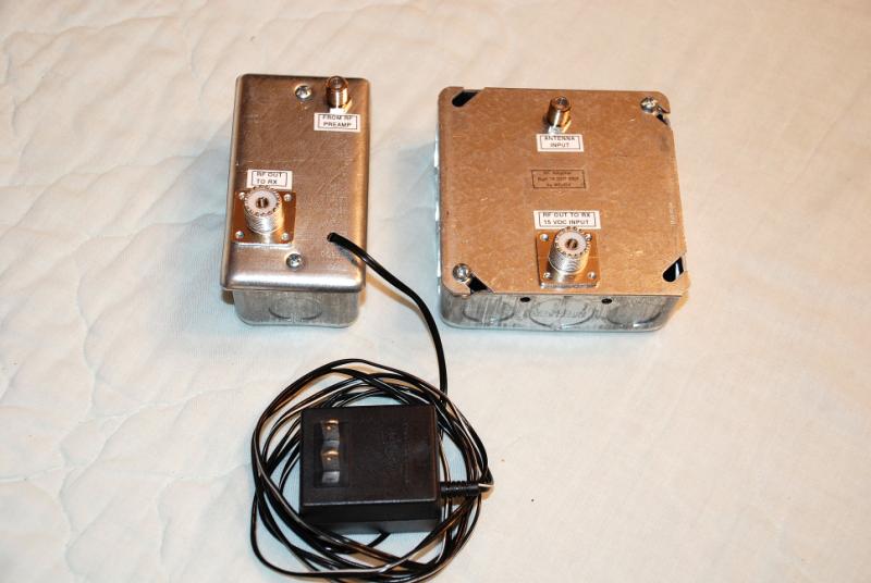
The finished amplifier is in the box on the right. The DC power injector is in the box on the left. For optimum results at HF, a 50 Ohm coaxial cable should be used to connect the two units. At LF and MF, just about any cable will work. I used some RG-6 coax cable for connecting the units to my tree antenna. The amplifier has ample gain, so feedline losses are not a problem. The RF amplifier and the power injector circuit boards are mounted on the reverse side of the cover plates of their respective enclosures.

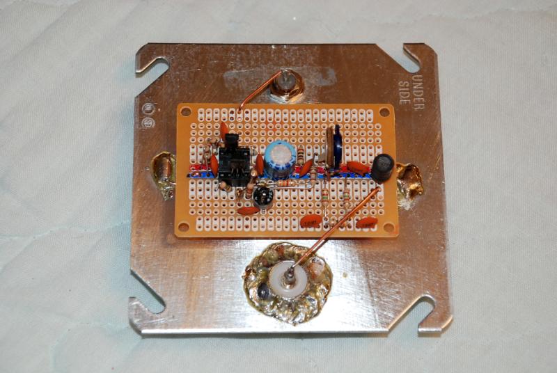
The amplifier is built on a small perf-board obtained at Radio Shack. Parts are placed as closely as possible to match the schematic diagram. Some variation in placement is necessary to fit all the parts in place. I used an 8-pin DIP socket to hold the transistors. That will make it easier to replace them when Mr. Lightning visits the neighborhood.
A steel electrical junction box is used for the enclosure. It is very well shielded, and is sturdy and best of all, cheap!
For the connection back to the power injector, a UHF-type chassis connector was used. This connector was soldered to the metal plate. It was easier to solder the connector in place than to use nuts and bolts. For the antenna connection, I used an "F" chassis connector. This allows me to simply slip a bare #16 to #18 AWG wire into the connector.

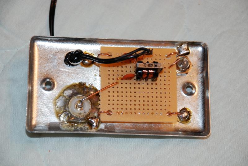
The inside of the DC Power Injector is simplicity itself. I used a surplus "Wall-Wart" DC power adapter for the amplifier power. Not having a suitable power plug and jack readily available, I just drilled a hole in the metal plate and ran the power wire through the hole, tied the wires in a knot, and soldered things together.
Note the use of the small common mode RF choke used to keep the RF out of the DC power supply lines. Again, as in the amplifier box, a set of UHF and "F" chassis connectors were used. Here, the "F" connector takes the coax cable from the power injector to the amplifier. The UHF connector goes to the receiver. I did that on purpose, because I use a 100' length of RG-6 cable with "F" connectors on both ends to connect the tree antenna to the hamshack. The through connector in the tuning cabinet on the tree antenna has an "F" connector outside, and a UHF connector inside, hence, house-to-tuner is "F" to "F", and tuner-to-amplifier is UHF to UHF. All clear now? <G>

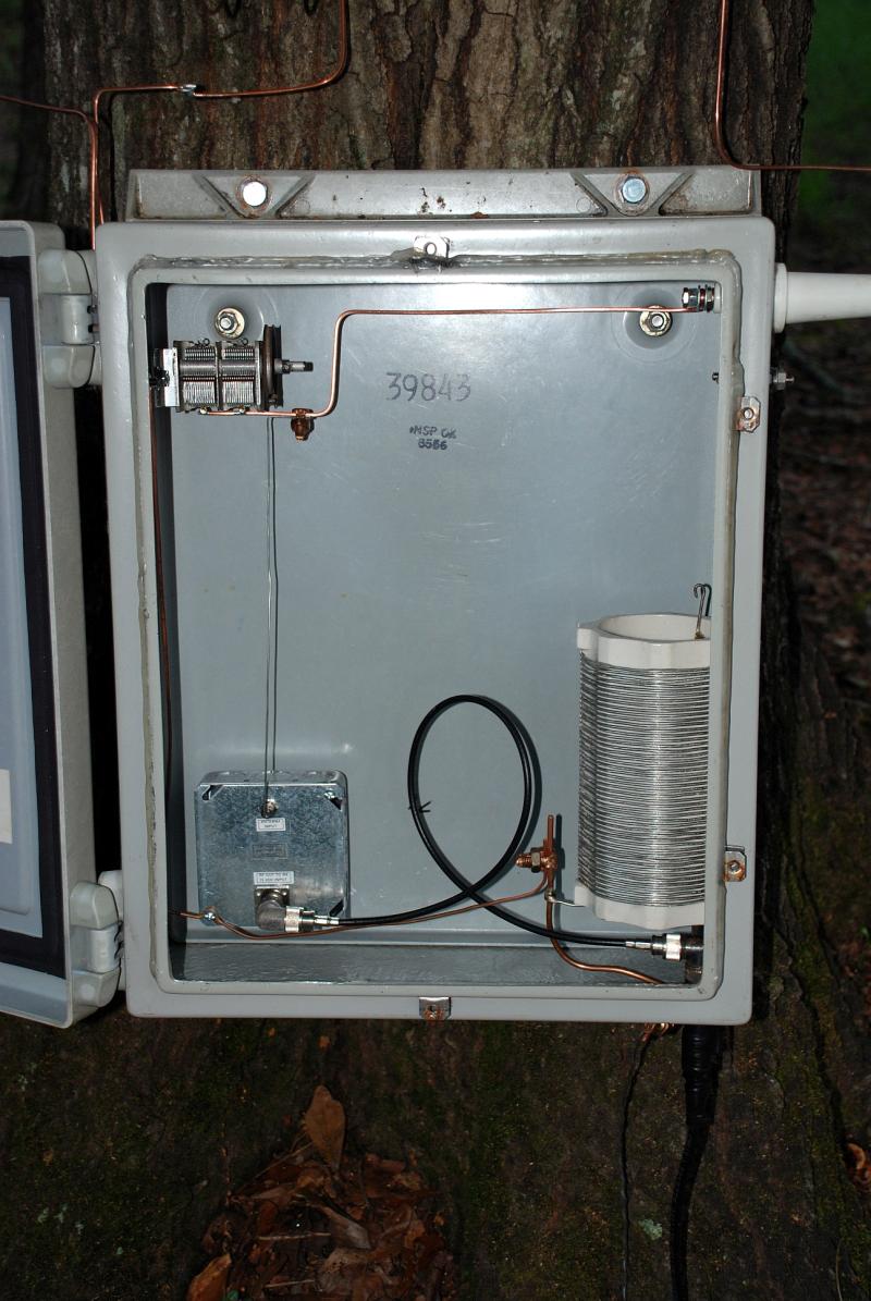
Here is the finished amplifier installed in the antenna tuning cabinet. As built, it delivers a solid 30 dB of gain, with a low noise figure, which is set by the J310 transistor. If you get excessive front-end noise, try another J310. they do not all have the same RF characteristics.
End Notes
- Download the original amplifier design article by KO6BB HERE.
Philip has a very good write-up on the functioning of the amplifier, and, with the exception of the DC power injector and the different bipolar transistor. his adjustment procedure works very well with my version.
Both versions include a 6 dB resistive pad in the output to ensure stability. The J310 front-end RF amplifier always runs "wide-open" for best noise figure. Variable overall RF gain is provided, so the output of the amplifier may be set as needed to compensate for feedline losses and your particular receiver setup.
In my station, I need to feed several receivers from the same antenna. I have found by testing, that some ordinary cable TV RF splitters will work quite nicely all the way down below 500 KHz. I have one of these attached to the output of this amplifier to feed two receivers at once. This amplifier has sufficient output to be able to drive as many as eight receivers simultaneously with an 8-port splitter.
- Download the schematic of my version of the amplifier HERE.
- Download the schematic of the DC Power Injector HERE.
- Download the specs on the J310 transistor HERE.
- Download the specs on the 2N5089 transistor HERE.
73,
Ralph - W5JGV - WD2XSH/7
[BACK]