A Homebrew 11.7 uHy Variometer
by W5JGV
Posted Jan 22, 2010, updated Jan 28, 2010
Just what you need to tweak your 600 Meter antenna.
This is an in-progress project!
I needed a simple variometer to be able to vary the inductance in the matching network for my 600 Meter vertical antenna. After considering several options, I decided to build a variometer using some easily obtainable parts. I did not need a lot of inductance change, about 10 uHy would work fine. The variometer described here allows a +/- 5.85 uHy swing while inserting a fixed 6.1 uHy inductance in the system.
I wanted to use heavy wire because the antenna current in my antenna system at resonance is about 10 amperes. I knew from experience that #6 wire would be the smallest size that would not overheat in continuous operation. I chose 1/4" OD copper tube for the stationary outer coil and #6 AWG solid copper wire for the inner rotary coil. The coils are double spaced for optimum "Q" and because since I threw this unit together in a hurry, I used some salvaged tube and wire which was not quite straight. Using a closer turns spacing would present the possibility of an accidental short circuit.
For the outer coil form, I used a PVC pipe cap for 6" PVC pipe. I carefully cut out the closed end of the cap to end up with a length of PVC about 4 1/2" in length. The inner rotary coil form is a slip coupling for standard 4" PVC pipe. A hole was drilled through both coil forms across the diameter of the forms for the shaft.
The adjusting shaft was made from part of a fiberglass chimney sweep extension rod. The fiberglass rod measures not quite 3/8" in diameter, so a 3/8" hole provided proper clearance for the shaft to rotate freely in the outer coil form. A slightly smaller hole was driller through the inner rotary coil, and the shaft was pressed through the coil form. Because the shaft has a tendency to slip on the smooth PVC of the inner form, a small hole was drilled crosswise through the fiberglass shaft just inside the inner coil form. A short length of #14 copper wire was inserted through the hole and glued against the inside of the inner coil form using RTV adhesive. Copper wire was used to avoid induction heating which would happen if steel or iron wire were used instead of copper.
To keep the inner rotary coil from slipping sideways and hitting the outer coil, two more holes were drilled through the fiberglass shaft lust inside the outer coil form, one on each side. Two additional length of #14 copper wire were inserted through the holes and bent into a "Z" shape. The "Z" prevents the wire from dropping out of the shaft, and prevents the shaft and the inner rotary coil from slipping sideways out of position.

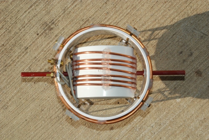
A top view of the variometer shows the just barely visible "Z" wire on the right side of the shaft, just inside the outer coil form. Note there is a plastic washer between the "Z" and the wall of the coil form to prevent scraping the coil form and causing binding.
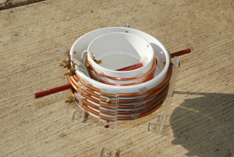
The variometer is shown in the position for maximum inductance. In this position the inductance of the two coils are additive.. If the shaft is rotated 90 degrees, the inner coil is "flipped" over and the inductances of the coils are subtracting, and the variometer is at minimum inductance.
Here the variometer is shown at 50% inductance. The inductance is adjustable between 6.1 - 17.7 uHy, for a variation of 11.6 uHy. Although the two coils have almost the same inductance - 5.6 uHy for the outer coil and 6.1 uHy for the inner coil when measured separately- the minimum obtainable inductance is 6.1 uHy. This is because the magnetic fields from the two coils do not completely interact.
Looking down between the coils, you can see the grey connecting wires between the inner and outer coil forms. These wires are required because the two coils must be placed in series with each other for the variometer to function. Obviously these wires are much smaller than the tube and wire used on the coils, and they will get hot from RF loss when power is fed through the variometer.
What I did was to parallel two lengths of #12 AWG high temperature wire. The wire originally has a woven jacket of fiberglass over the grey insulation you see here. I removed the fiberglass because it made the wire much stiffer and increased the diameter.
The grey insulation is a Silicone rubber jacket that easily withstands the temperature of molten solder. Placing two wires in parallel will reduce the heating by dividing up the RF current flowing through the wire. Each pair of wires is wrapped around the shaft twice. When the inner coil is rotated 1/2 turn, the inductance changes from minimum to maximum, and the wires unwind by one turn. By wrapping the wires around the shaft, very little stress is placed on the soldered joints at the end of the wire and the center portion of the wire is flexed fairly evenly. As a result the connecting wires should last for many adjustment cycles.

There are four plastic legs that support the variometer. They are made from 3/16" thick Plexiglass. They are attached to the outer coil form by two brass screws that pass through clearance holes that are drilled through the leg. These screws then screw into threaded holes in the wall of the outer coil form. To add additional strength to the leg, a backup section of plastic is placed against the portion of the leg where it covers the windings of the outer coil. Heavier plastic could be used for the legs - I just happened to have a lot of this thickness plastic on hand, and already bent to shape.
NOTE THAT ONLY BRASS HARDWARE MAY BE USED WITH THIS VARIOMETER.
Use of ferrous hardware will result in severe induction heating of the hardware and possible melting of the plastic.

Note that all the hardware seen here is brass. no steel or iron allowed!!
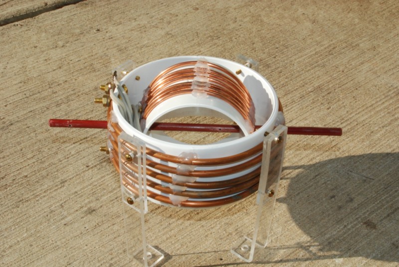
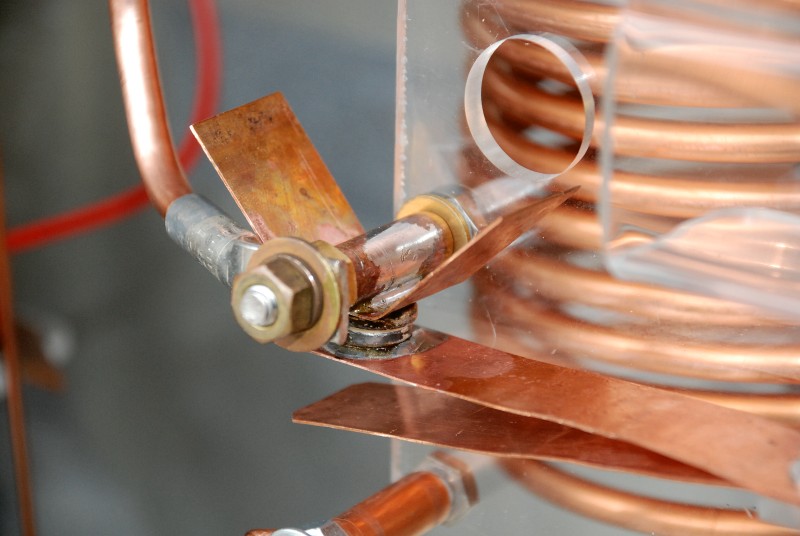
The RF flow through the variometer is as follows - One external RF connection is made to the 1/4" brass bolt barely seen at the bottom center of the photo. After passing through the outer coil, the RF goes from the right hand 1/4" brass bolt at the top of the outer coil through one pair of flexible leads to one end of the inner coil. After passing through the inner coil, the RF exits through the second pair of flexible leads and ends up on the left hand top 1/4" brass bolt which is the second external connection of the variometer.
If you look at the fiberglass shaft where it enters the inner coil form at the top of the picture, you can see the copper wire that is used to hold the shaft to the inner coil form. Also visible ion the picture is a lot of RTV adhesive that was used to hold things in place. The RTV adhesive is a good choice as it is heat resistant and flexible, allowing the tire and tube to flex slightly as the coil heats up in operation.

All wound up, and no place to go but up.
This photo shows the variometer in the minimum inductance position with the connecting wires wound twice around the shaft.

Here the variometer has been set to 1/2 inductance position. You can see that the wires are slightly unwound from the shaft.
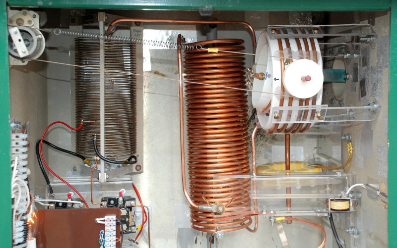
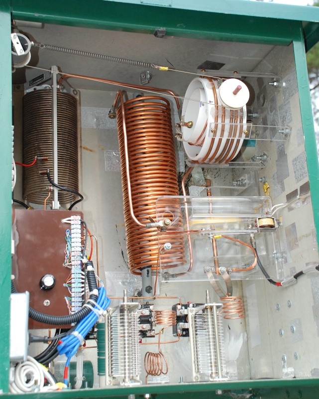
Here is the completed variometer installed in the antenna tuning cabinet at W5JGV - WD2XSH/7.
The matching system for the 600 Meter antenna consists of two loading coils in series. The first coil, at the left of the picture, is an edge wound copper coil. The black wire connecting to the tap on the lower portion of the coil adjusts the total amount of inductance in the system, and sets the resonant frequency of the antenna system. The red wire is the feed point tap from the transmitter, and adjusts the load impedance for the transmitter.
The top of the edge wound coil is connected to the input of the variometer with a length of 1/4" copper tube. the output of the variometer is connected with 1/4" copper tube to the bottom of the right hand coil, which is wound with 1/4" copper tube. The connection from the top of the copper tube coil to the upper (600 Meter) contact of the antenna changeover relay is made with 1/4" copper tube.
The antenna changeover relay is constructed from a relay coil salvaged from a surplus high voltage relay. I installed the coil upside down on a plastic frame. The armature of the relay is extended by a length of plastic. The armature extension holds a pair of copper strips which are connected to a length of flexible copper wire. The flexible wire goes to the antenna through the RF current transformer which is used to measure the antenna current. The copper strips are work hardened by repeated flexing, then flattened and bent apart slightly to allow spring action when the contacts make and break during operation.
The lower fixed contact is a length of copper tube, against which the copper strip rests when contact is made in the lower (deenergized) position of the relay. The upper (energized) contact was originally the same as the lower contact, but due to the high current encountered during full power operation at 600 meters, the copper to copper contact burned badly and failed. This was replaced by a set of coin silver contacts which were soldered on to the copper strip and the copper upper contact tube.
Also visible is the variometer drive motor on the left side of the cabinet and the plastic coated stainless steel fishing leader and tension spring that is used to rotate the variometer. The white drive wheel on the avriometer was fashioned from a 1/2" thick peice if HDPE plastic. It has a slight half-round groove to prevent the drive wire from slipping off the wheel. Two 1/4" diameter brass set screws were made to attach the wheel to the fiberglass drive shaft. The set screws are inserted into drilled and tapped holes spaced 90 degrees apart through the drive wheel.
This view shows the antenna changeover relay and the matching networks which were used for matching the antenna on the 40 and 20 meter bands. They are not used at this time.
The 600 Meter antenna changeover relay contacts are shown here in the closed position. the contacts are 1/2" in diameter and 3/16" thick. A :V: shaped copper strip has been soldered on to the stationary contact to act as a additional heat sink for the contact.

The 600 Meter contacts are in the open position, note that the lower contacts for 160 - 20 meters are in the closed position.
I hope this project will give you some ideas about how you might construct a variometer for your antenna system. If you need a really BIG variometer, check out this one and HERE and HERE that I built for my 166.5 KHz antenna system.
73, Ralph W5JGV
[Home]
The entire contents of this web site are Copyright © 2002 - 2010 by Ralph M. Hartwell II, all rights reserved.