A Ten Gallon Loading Coil - Variometer for MF/LF
( A Home Depot Special )
by W5JGV
Last updated February 15, 2002
If you want to print this page, please click HERE for a printer friendly version of this article.
Since I am confined to using a small suburban lot for all of my antenna installations, I have a problem installing anything really effective for use on 500 KHz or lower. Just about anything I plan to use as an antenna will require a serious loading coil. I decided to construct an experimental loading coil and variometer unit suitable for antenna testing and low power low frequency operation.
Since this unit was to be designed for mostly testing, I decided not to spend a fortune on Litz wire or exotic coil form materials. Instead, I chose the tried and true "Bucket Full of RF" approach and used a couple of 5 gallon paint mixing buckets which are readily available at most hardware supply stores for just a few dollars each. The buckets are manufactured from Polyethylene plastic, and has a very low RF loss factor. The loss of the THWN insulated wire is much higher, but at frequencies below 500 KHz is satisfactory for most amateur power levels. For wire, I chose inexpensive #14 Gauge solid THWN insulated wire, which is also available at most hardware suppliers.
I decided that for test purposes, the unit would probably work best if I could use a variometer as well as a series of selectable taps on the main loading coil for inductance adjustment. I chose the series of fixed taps so that each tap represented slightly less inductance change per tap than the adjustment range of the variometer would provide. By using a combination of the taps and the variometer, I could obtain a continuously variable inductance of approximately 150 microhenries to 3 millihenries. The trade-off to this wide range of adjustability is that there is a slight loss in coil Q and an increase in the loss resistance of the coil because of the taps and the changing form factor as the coil taps selected. However, for experimental use, it would be a decidedly useful device.
On with the construction!

After a midnight trip to Home Depot for coil components, I started by bolting the two buckets bottom-to-bottom by using 6 1/4" stainless steel bolts. Brass hardware would be better, but I has stainless hardware handy, and because of the small mass of the hardware the RF loss is not that bad. I also placed a flat washer on either side of the bolted joint to prevent the clamping stress from causing fractures in the Polyethylene plastic buckets. Note the variometer shaft holes which are cut in the side of the top bucket.

This view shows the position of the bolts used to fasten the buckets together. Note the variometer shaft holes in the bucket walls.

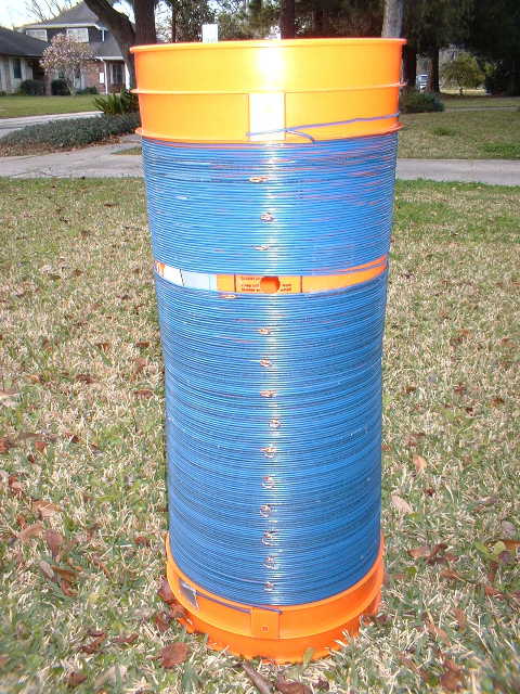
It may not look like it, but this photo shows the results of just one hour of wire winding work and a total of 500 feet of wire! Note that the upper part of the coil is separated at the point where the variometer shaft passes through the bucket wall. A total of 14 taps plus the start and end of the coil winding are visible in this photo. In practice, it was found that the upper two taps were ineffective since most of the variometer coil windings are below the upper taps. You may omit the top two taps when you build your unit.

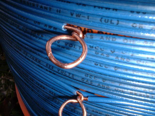
A close up view of the variometer shaft hole and several of the coil taps. Note that the tap closest to the variometer shaft has been offset slightly to prevent interference with the variometer shaft.

A close up view of a coil tap. The tap was formed by removing about three inches of insulation from the wire as it was being wound on the bucket, and then grabbing the center of the bare wire with a pair of regular pliers and twisting the wire through 360 degrees. The wire winding then continues on to the next tap. Nothing is used to hold the tap in position; the stiffness of the wire handles that problem. The taps are spaced every 12 turns.

Next, the Variometer Coil was built. This consists of two black ABS plastic 4 1/2" drain pipe slip couplings glued together. I used fine sandpaper placed on a plane table and using hand pressure to press the end of the couplings against the sandpaper, I smoothed the ends of the couplings until there was no light visible through the gap between the couplings when they were pressed together end to end. I then used ABS solvent cement to glue the couplings together. This results in a sturdy coil form measuring 5" in diameter by 8" long. This assembly will comfortably rotate inside the 5 gallon bucket. Although it is commonly not recommended to use black ABS plastic for coil forms, my tests showed that the loss at 500 KCs is almost zero when compared to an air core coil. At higher frequencies, however, all bets are off!

A carefully centered hole is drilled through the walls of the variometer form and filed to fit a length of 3/4" ABS sprinkler riser pipe. The threads are left on one end of the pipe so that a tuning shaft extension may be connected to rotate the variometer coil. The opposite end of the pipe is cut to length, the threads removed, and the interior reamed with a tapered reamer or a pocket knife so that the variometer lead-out wires will not be chafed when the coil is rotated.

This view shows the manner in which one end of the variometer coil winding is fed through a hole drilled in the wall of the coil form and connected to one of the two flexible wires leading through the shaft. The other end of the coil winding is treated similarly.

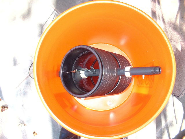
Here you see a top view of the completed Variometer Coil assembly. The shaft is glued to the coil form using ABS solvent cement. Two white ABS plastic rings about 5/8" long are cut from a section of Schedule 40 1" PVC plastic pipe. A single cut is made through one side of each ring to allow the rings to be slipped over the ends of the coil shaft. Be sure to put the inner rings on the shaft BEFORE gluing the shaft into the coil form!! Glue the rings against the inner coil form wall and to the shaft for strength. Two more rings are placed on the shaft outside of the coil. These are slid into position so maintain the correct spacing between the variometer coil and the walls of the 5 gallon bucket.

It's time to stuff the bucket with some inductance! Feed the variometer coil wires through hole in the bucket wall on the opposite side of the bucket from the coil taps. If you have chosen the shaft length correctly, a bit of shoving and bucket-bending will allow the shaft to pop through the hole. After fitting the threaded end of the shaft through the shaft hole nearest the coil taps, center the variometer coil in the bucket and slide the white retaining rings against the inside walls of the bucket. It is not necessary to glue these rings in place as the tension of the plastic rings should be sufficient. If they are too loose, remove them and replace them with longer rings. The longer the rings are, the stiffer they will be. NOTE: If you glue the ring in place, you may not be able to remove them should you need to make changes to the variometer.

This is what the wire side of the variometer shaft should look like when you are done.

And this is what the other side looks like when you have the tuning shaft extension attached.

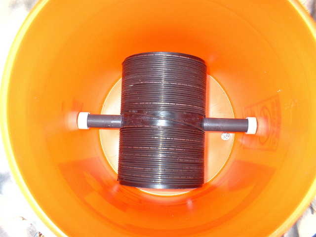
A view of the completed assembly with the Variometer Coil tuning shaft extension in place.

The Variometer Coil set to the maximum inductance position. Note the hole drilled in the coil shaft to allow the Variometer Coil connecting leads to exit the coil bucket through the tuning shaft at the left side. The retaining rings are shown against the bucket walls.

Here's the Variometer Coil at the 90 degree position. Note that it just clears the bucket walls.
CONNECTIONS:
One wire from the Variometer Coil goes to your antenna, and the other Variometer Coil wire connects to the top end of the bucket winding. Connect the bottom end of the bucket winding to your feedline or whatever.
I suggest adjusting the taps by placing a shorting jumper between the bottom of the bucket winding and any given tap to short out however many turns you wish removed from the circuit. I know theory says that this causes some loss of Q, and increases coil losses somewhat due to the signal lost in the shorted turns, but in practice - and confirmed by measurements here - the loss is not too bad, since the coil uses low resistance wire, and the Q is not that good to start with.
Shorting the unused turns also prevents an accidental Tesla Coil effect where open ended turns by chance resonate at a harmonic of the operating frequency or at the frequency of some other unwanted signal, causing problems when receiving. YMMV, but you ARE experimenting, anyway!
Let me know how your Ten Gallon coil turns out.
73, Ralph W5JGV
If you want to print this page, please click HERE for a printer friendly version of this article.
[Home]
The entire contents of this web site are Copyright © 2002 by Ralph M. Hartwell II, all rights reserved.