
Sept 8, 2007 - By W5JGV (updated January 01, 2008)
"Why put up an antenna when they're growing all around you?"
There are two antennas in this picture and one of them is not made of metal. Can you find them both?
If you look carefully, you can just see the horizontal single wire antenna in the background in the far right side of the picture. That is my 160 meter dipole antenna, which is about 20 feet above the ground. The other antenna is the large Oak tree in the center of the picture. Near the base of the tree trunk is the coupling coil which surrounds the trunk.
Yes, the tree IS the antenna!
My interest in tree antennas goes back many years, when I first read about some experiments using coils to couple RF energy to trees. Unfortunately, I neglected to save the article, and it was only much later that I was able to locate the source for the article.
Here are four articles that explain tree antennas - George O Squire Tree Antenna Patent.pdf - 1975 January Ikrath IEEE tree antennas.pdf - Robert Hand article.pdf and Signal Propagation at 400 kHz Using an Oak Tree with a HEMAC as an Antenna AD735330.pdf
It appears that there are two methods generally used to connect to a tree for using it as an antenna. The first is to drive a nail into the tree some distance up from the ground, and the second is to use a coupling coil around the trunk close to the ground. Since I prefer not to climb trees unless I really have to, I decided that the coupling coil would be the better approach.
Since little, if any, design data has been published on tree antenna coupling coils, I took a guess at what might work for the coil dimensions. I guesstimated that using a coil with about half the diameter of the tree trunk would be about right for the coil diameter. The length of the coil would be the diameter of the tree trunk. The number of turns was an unknown, but I figured that if the inductance was too small the tuning would be very sharp, and changing environmental conditions, rain, temperature, etc., might cause tuning problems. A larger inductance would be less sensitive to such things.
I decided on an inductance of about 175 uH as a starting point. That would require a coil of about 75 turns of about 10 inch diameter, or a total of about 195 feet of wire. Since I had a lot of #10 AWG bare copper wire available, that was used for the construction of the coupling coil.
Tuning the coil to resonance at 505 KHz would require approximately 575 pF of capacitance. At resonance, the coil losses would be about 10 Ohms, which would not be too good for transmitting, but for receiving, it should not pose a problem. At resonance, the impedance of the circuit would be about 30 Kohms so it would be a fairly good match for FET RF preamplifier.
Designing the coil was one thing, but how was I going to hold it in place against the tree? It had to be held away from the bark, or losses would increase when the tree got wet in the rain. After wearing out several pencils and using up the back of a lot of old envelopes, I finally hit on the idea of dropping each turn of the coil into a series of parallel slots cut into a length of plastic pipe. Then, when I bent the pipe around the tree, the flexing of the pipe would cause the slots to close up slightly and squeeze the wire tightly between the sides of each slot. At that point, all I'd have to do was to manhandle seven feet of flexible pipe and a hundred loose turns of copper wire into place while screwing the whole thing firmly to the tree trunk. I figured I'd work on that little problem after the coil was built.
Time to start construction!

Construction of the coupling coil was started by running a broomstick through a roll of Bonnie, KB5YSE's art studio wrapping paper and supporting the roll between two wooden chairs. The roll measures about 9 inches in diameter, and made a solid form on which to wind the #10 AWG bare copper wire for the coil. The free end of the wire was simply taped to the roll of paper and winding was begun. After about 90 turns were wound on the form, the coil was carefully removed from the form and set aside for later installation.

The wire I used was left over from a commercial AM broadcast antenna installation I did many years ago. It is bare, soft drawn, #10 AWG pure copper wire. It was just right for a coil of this size, since it is strong enough to hold its shape without any extra support.

Here is the finished winding while it is still on the winding form. It looks neat at this point, but as soon as I loosened the wire to remove it from the form, it promptly sprang into action and unwound into a larger diameter shape, and instantly piled up into what appeared to be a massively tangled heap! Fortunately, it was very easy to unravel, and placement of the wire coil onto the supporting tube went along without any unexpected difficulty.

All that wire has to be supported somehow, and I figured the easiest and cheapest way would be to take a length of 1" diameter plastic pipe and cut an evenly spaced series of slots into the pipe. As the pipe was bent around the tree and fastened in place against the tree, the slots would close up slightly as the pipe was bent. This would "put the squeeze" on the wire and hold the coil firmly in place. I drew a series of pencil marks spaced one inch apart on the pipe. The slots were then cut a little more than halfway through the pipe using a carbide tipped saw blade on a table saw. I made a "sled" for the saw to hold the pipe tightly in position as I cut the slots. The use of the sled also kept my fingers well away from the saw blade during the cutting process.

Well, here's the coil in place around the trunk of the tree. I'd like to say that the uneven placement of the ends of the tube were to ensure proper drainage of water from the tube when it rains, but in reality, I just screwed up a bit and didn't line things up quite right. ( Hmm... I think I like the rain drain idea better! )

Seen from the other side of the tree, the coupling coil looks a bit better. The black screws that hold the pipe against the tree are not tightened up snugly. You must allow some slack here, or as the tree grows it will crush the pipe and eventually pull the screws right through the pipe, ruining the coil.
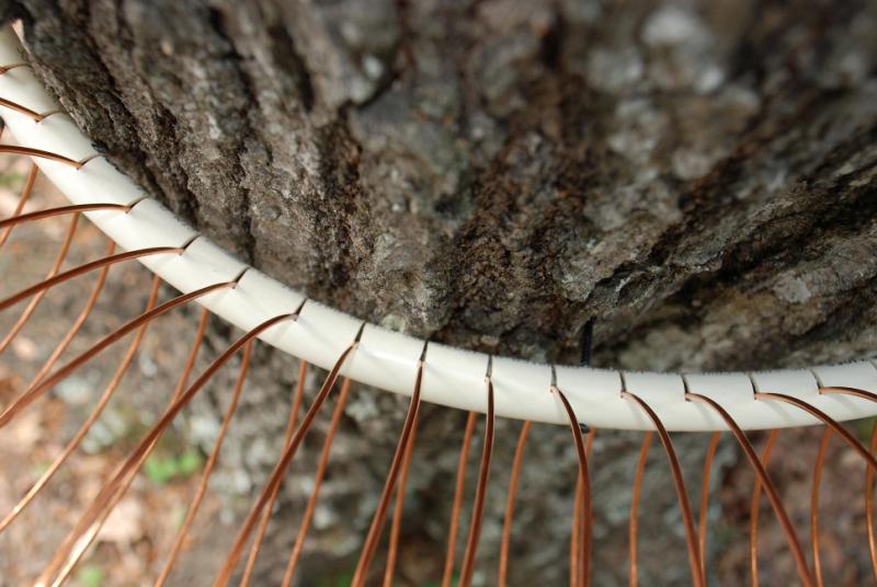
In this top view of the support pipe, you can see how the slots close up as the pipe is bent around the tree. As the slots close up, they pinch the turns of the coupling coil tightly. After the pipe is fastened in place, you cannot pull any of the turns through the slots. It's tight! The difficult part is that each turn of wire must be hand adjusted as the turns are placed into the slots. Of course, while I was doing this, about six other turns were trying to jump out of their slots. It turned out to be a real "juggling act" to get the turns to stay in place as I assembled the coil, but I finally beat the recalcitrant coils into their proper positions; order prevailed, and I got the coil finished at last.

Tune up time! Does it actually work?
A quick test setup was made using a portable radio and an old 435 pF dual section variable capacitor salvaged from a defunct broadcast receiver. The coil resonated with the calculated amount of capacity connected across it. As it eventually turned out, this was about the easiest way to tune the antenna. All I have to do is to position the portable radio antenna close but not touching the coupling coil. The radio is then tuned to the frequency at which I want to tune the antenna. When the coupling coil is tuned to resonance, the signal (or background noise) in the radio increases, indicating that the system is tuned to resonance at that frequency.

After the first tune up was so successful, I quickly constructed the elaborate weather cover you see here. Slits were cut into the bottom of an empty plastic water bottle and the tuning capacitor and feedline connections were stuffed into the bottle. This setup, complete with the Radio Shack clip leads, was used for several days before a more permanent enclosure was installed.
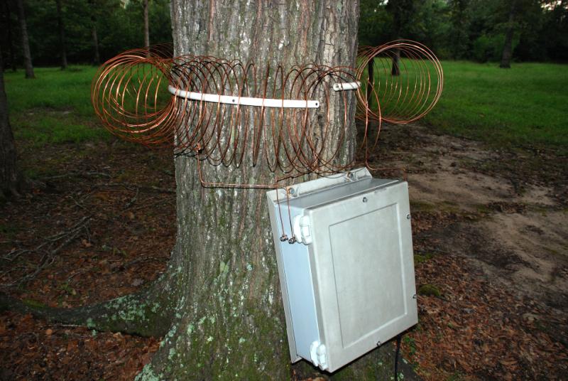
Now, this looks more like it! The enclosure is one that I salvaged from my Katrina-ravaged tower at my old QTH in New Orleans. The cabinet is at least 30 years old (Hoffman makes good stuff, you bet'cha!) and has been out in the sun and rain all those years. It is still weather tight using the original gaskets. It is Fiberglass and was starting to shed glass strands, so I refinished the outside of the enclosure.
There are two connections visible on the left side of the enclosure. The connection closest to the tree goes to the left ("cold") end of the coupling coil. This end of the coil is also connected to ground. The front-most connection goes to a tap on the coil that is 10 turns from the ground end of the coil. This is the feed point for the 75 Ohm coaxial cable that goes to the receiver in the shack.

A close-up view of the tap and cold end of the coil connections.

Stainless steel through bolts carry the signals through the Fiberglass walls of the enclosure. Sealer is applied to the bolts so that rain will not enter the enclosure. The bolts that hold the enclosure against the tree are not snugged up tight, there is room for the tree to grow. Both the bolts holding the enclosure to the tree and the screws holding the coupling coil in place will have to be backed out slightly every year or so.

The ground system for the coupler uses three steel screws that are driven into the roots of the tree. I figured that the tree probably has a better connection to the ground than I could manage to get by driving a ground rod. After running the screws into the roots, the screws are removed and the end of an aluminum wire are pushed down into the holes. The screws are then replaced. This gives a good connection to the damp wood. Do NOT drive copper or brass wire or screws into a live tree, as the copper may kill the tree. Iron, steel or aluminum is OK.

At the center ground-root, the wires from the other two ground-roots and the twisted pair of ground wires from the coupler circuit all come together. All the wires go about two and a half inches into the tree root. I used aluminum electric fence wire for the ground wires.

The ground wire goes from the tree roots to the coaxial connector on the bottom of the tuner enclosure.

A split-bolt wire connector connects the ground wire to the pigtail coming from the connector.
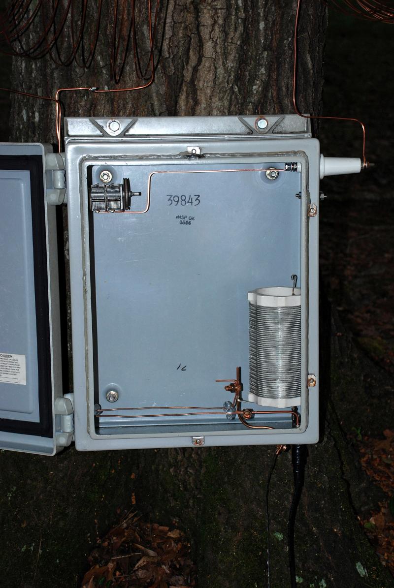
As you can see, the enclosure is mostly empty space. A much smaller cabinet could be used, but this one was available and didn't cost me anything

The frame of the tuning capacitor is simply bolted to an aluminum angle bracket and fastened directly to the grounded through bolt. Since the capacitor frame is grounded, I cam simply grab the dial cord drum on the end of the capacitor shaft and turn it as needed to adjust the capacitor.

Both sections of the capacitor are in parallel, and connected to the wire leading off to the right of the picture. That wire goes through a ceramic feedthrough insulator on the right side of the enclosure and then connects to the hot side of the coupling coil.

The wire closest to the back of the cabinet is the ground wire between the cold end of the coupling coil and earth ground. The wire nearest the front of the cabinet connects the coil tap to the center wire of the coaxial cable going back to the shack. Two spacers made from vinyl plastic tube that were used to hold the parallel wires in place.

I had previously installed this 100 uH coil in the enclosure to be used as part of a shunt feed tuned for my old tower on 75 Meters.
However, even after much tinkering, it never worked properly, so I abandoned that project. It was only after removing the coil to refinish the enclosure for this tree antenna project that I realized that the cause of the problem was. It seems that when I wound the coil, I covered the winding with what apparently was a VERY good clear varnish, because it prevented the E. F. Johnson squeeze clips that I used from making contact with the wire! No wonder it would not work!! All I can figure out is that I must have had total brain fade when I built the tuner. I left the coil in the enclosure, since it just looks so nice. <G>

Except for the RF preamplifier, this is the finished system. I simply ran the coax cable over the ground and back to the shack. It's easy to change if I need to, and the lawn mower misses it. In a year or so, the grass will have grown over it and it won't be noticeable.

While working on the tuner, I noticed this little guy walking across the turns of the coupler coil. If he had been parallel to the turns, I probably would never have noticed him.
CLOSING THOUGHTS -
- The tree I chose for this project is about 90 feet tall. There are others available that are taller, or more in the clear, or both, but this one was in a good spot for testing. It is far enough from the house so as not to pick up much "house noise" but close enough so that I can get a long extension cord out to it to run test gear. I may try a different tree at some point.
- I suggest using aluminum electric fence wire or aluminum clothes-line wire for making the coil. That would make the coil lighter and easier to handle during construction, and the losses in the coil will not be enough greater to worry about. One advantage of the #10 bare copper wire is that it fits perfectly in the slot cut by the circular saw blade. Other types of wire may require a different width slot and considerably more construction effort.
- I strongly suggest that you drill the holes for the mounting screws through the plastic support pipe BEFORE you try to attach the coil to the tree, unless you have at least six hands to hold everything.
- Having an extra person available when you attach the coil to the tree is a great help. I did it all by myself, but I waited until the dark of the moon, on a Tuesday, and I held my tongue >just< so. ;)
- I did not use any isolation transformers between the coupling unit and the coax feedline going back to the ham shack. I did not see any extra noise pickup from the coax cable either with or without the cable grounded at the tree end of the cable. Your installation may be different, of course. I happen to have (finally!) a very low RF noise QTH.
- This coupling coil was designed for MF operation. The tuning range of the coil with the capacitor I used is from roughly 428 KHz to 1150 KHz. No detuning of the system is noticed unless you bring your hand within a few inches of the hot end of the coil. A coil with fewer turns would probably work better for HF work.
- The signal pickup of the tree antenna seems about equal to or a little less than using one side of my 160 meter dipole antenna, which is about 20 feet high. It does seem to pick up a little less noise than the dipole, so the S/N ratio appears better overall. I have not had the tree-tenna in use long enough to make any accurate conclusions.
- I have not noticed any difference in signal pickup from day to night, nor does rain seem to change the antenna characteristics.
- Tuning of the antenna may be done by using the variable capacitor or by shorting out one or more turns of the coil on the "cold" end. This raises the operating frequency but does not seem to change the sensitivity of the antenna appreciably. Since the "cold" end of the coil is grounded, a simple relay arrangement may be used to short out some of the coil turns to ground to make frequency shifts remotely.
- The antenna works even better since I installed my RF preamplifier.
73,
Ralph - W5JGV - WD2XSH/7
[BACK]