A Shielded Low Frequency Loop Antenna
for W5JGV - WC2XSR/13
Allows Simultaneous Transmission and Reception at the Same Site.
This page last updated February 12 2004
I had not given any thought to low frequency (LOWFER) operation since I became a ham, but when the 600 Meter Research Group started talking about trying to obtain a Part 5 Experimental license, I jumped at the chance to be a part of it. Although the original frequency range was in the 450-500 KHz band, the group also obtained an authorization to operate down at 166.500 KHz, with 400 watts transmitter power output.
Since I had never had the opportunity to work with low frequency transmitters, I thought this would be a practical learning experience. It was, and still is. Although it's a bit of fun to "reinvent the wheel" so to speak, I find it's a lot more practical to read the old books and literature and see how the "old timers" did things way back when the big boys used these frequencies.
One of the things I found out was that for best results, you needed a BIG antenna and a BIG ground system. Well, I don't have room for either one on the minuscule piece of ground I call home. However, coming from hard-headed ancestors, I figured that just because "everyone" said that I could not make low frequencies work with a small antenna, I was going to do it anyway. So, I built my vertical antenna, with a poor ground system, and managed to get a signal out across the USA fairly well.
As part of the 600MRG project, low frequency propagation studies were in the works. I quickly found out that there existed a fairly large and active group of Part 15 operators - the LOWFERS. I decided that using their signals as propagation indicators would be a good addition to the 600MRG effort. Using my low frequency vertical transmitting antenna for receive, I quickly snagged some of the LOWFER signals. But, with only one antenna, it is virtually impossible to transmit and receive at the same time. What to do?
I spent a lot of hours with EzNEC designing the vertical antenna, and chose it over a loop antenna because of space limitations. However, I found that when it came to receive operation, a loop had possibilities. I mentally filed that information and continued on with other projects. When I started to seriously consider the possibility of being able to receive while transmitting, I started crunching numbers again. Things looked better than I had hoped!
I am operating WC2XSR/13 under the 600MRG Part 5 FCC authorization on 166.500 KHZ at 400 watts transmitter power output. I decided that I would like to be able to receive on the "watering hole" frequency of 185.3 ±. This is a frequency separation of 18.8 KHz, or about 10.68%. Pretty close, but possible, according to the numbers.
Since the ERP of the WC2XSR/13 antenna system is less than two watts, the total radiated RF power is not very high, but the separation between the transmit and receive antennas would also very small, about 25 feet at most, because of the small lot I have.
A little antenna theory here - a base-fed quarter-wave vertical antenna operating over a good ground system will have the E (electric) and H (magnetic) fields close to balanced, that is, the E field and the H field will have the same relative energy levels. (They are measured in different units, of course.) The very short vertical antenna used here for WC2XSR/13 and at some LOWFER stations does not meet that balanced field criteria. In fact, the ratio of field strengths is extremely lopsided. These electrically short antennas have very high E fields and very low H fields. That's why you can light a fluorescent bulb near a LOWFER antenna when the power level from the transmitter is one watt - the short vertical antenna has a huge electric field intensity, but a very low magnetic field strength. The unbalanced field strengths result in poor radiation from the antenna.
It's just the reverse for loop antennas - they have high H field strengths and low E field strengths. That is, lotsa' amps through the loops at low voltage, whereas the verticals have few amps and caged lightning bolts for voltage.
The end result of all this theory and number crunching indicated that I might just make this work if I combined a vertical transmitting antennas (which I already had) and a well-shielded loop antenna for receive. My reasoning is that since the transmitted E field is very high, proper use of shielding should reduce that signal to almost zero, leaving just the transmitted H field to deal with. If the loop is properly built and carefully oriented with respect to the transmitting antenna, it should be possible to null out most of the H field as well, leaving us with only the desired signals.
Could it be done? I quickly assembled a ten foot X frame and built a single turn square loop of unshielded #12 wire. This loop was then threaded once through a #43 ferrite core which had about 15 turns of wire as a secondary connected to a receiver. The loop wire was not connected to anything else, so that except for about 2 pF of capacity to the transformer winding, and E field picked up by the loop should be ignored. I placed the test loop about 20 feet away from the transmitting antenna. When I tuned in local broadcast stations, NDB's and WWVB, the loop exhibited the classic figure-8 pattern, with two very deep nulls located 90 degrees away from the major lobes. So far, so good! Next, I fired up WC2XSR/13 at 400 watts into the vertical antenna and rotated the loop for minimum signal pickup on 166.500 KHz. I found that I was able to obtain about 45 dB reduction in signal strength. Very good!!
The results of this test convinced me that what I wanted to do was possible. Time now for some serious number crunching and construction! I had available enough 7/8" Heliax© coaxial cable and enough 1/2" Aluminum CATV hardline to make a two-turn loop out of either type cable. Calculations indicated that while the Q of the Heliax would be higher than the Q of the CATV cable, the difference was probably not enough to make up for the very considerable weight difference of the finished loop. I decided to use the CATV cable for the antenna.
At this point, I had to decide whether to use the outer shield or the inner conductor of the CATV cable as the loop conductor. Using the shield would result in a calculated Q of about 250, but would also mean the loop would be unshielded, making E Field cancellation a bit dicey. Using the inner conductor would drop the calculated Q to about 175, increasing the bandwidth and reduce the received signal strength slightly. On the good side, it would also me to use the CATV cable's shield as a shield from the transmitted E field. I decided to use the inner conductor and make it a shielded loop.
How many turns should I use? More turns means more received signal, but more weight and difficulty of construction. The Q does not change enough to really matter with the number of turns, so that was not a real consideration. More turns also means more distributed capacity due to the increased length of the cable forming the loop, thereby reducing the highest frequency that the loop may be tuned to. Two turns seemed like a reasonable compromise, so I constructed the loop antenna with two turns. Here's how I did it, and how it turned out...
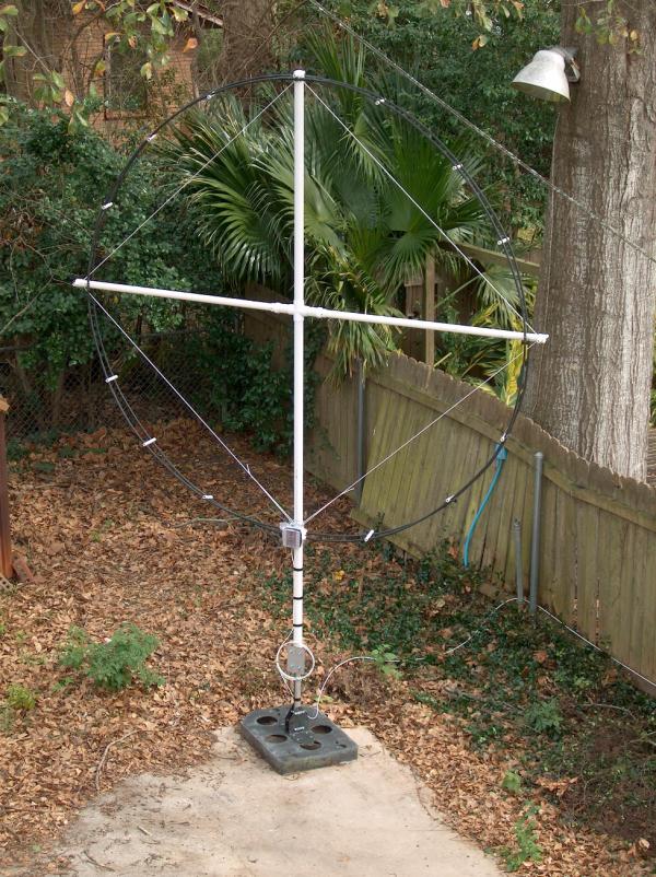
The W5JGV Loop Antenna
This is the completed antenna. In this view, you can see the PVC pipe mast and cross-arm assembly which supports the two turn CATV cable loop. The PVC sections are held in square alignment by the use of a continuous length of sunlight resistant Polyester rope. The turns of the loop are held in position by using short notched lengths of 1/2 inch PVC pipe. There is one turn of the loop on either side of the PVC pipes. The grey metal box at the bottom of the loop houses the tuning capacitor bank and the ferrite core matching transformer. The white coaxial cable running along the fence takes the signal from the loop antenna and carries it into the house to the receiver. The extra coax coiled up and hanging on the support mast of the antenna is simply excess cable in case I want to move the antenna to another location in the yard.

The Cross-arm assembly. The vertical section is made from 2 inch diameter schedule 40 PVC pipe. It extends 5 feet above and below the center joint. The outer part of the horizontal arms are made from 1-1/2 inch diameter schedule 40 PVC pipe.
The center cross "T" is 2 inch on all four arms, so a short length of 2 inch diameter PVC pipe is used to extend the cross-arms slightly. I made these a bit longer than they needed to be just in case the pipe cracked and I have to cut the broken section out and splice the cross-arm. That decision was an "Oops!" as I will explain later...
Note that there are a couple of black spots visible on the outer ends of the reducing fittings. What they are is a set of four 7/8 inch long drywall screws that I screwed through the joints in order to add a bit of mechanical strength to the joints. One of the joints cracked loose when I handled the plastic frame a bit too roughly, so I re-glued it and added the screws.

This is the portable base and support mast for the antenna. The black base is a heavy cast aluminum base that was used for a 16MM television film projector, which has long since gone to that great salvage yard in the sky. I found a pair of heavy steel "L" brackets, that measure about 6" x 6" x 3/8" thick. They has some holes already drilled in them that I was able to use, so I drilled holes through the aluminum base and bolted the "L" brackets to the base.
The vertical mast is two sections of 1-1/2" steel water pipe. The lower section is about 20 inches long, and the top is threaded and fitted with a coupling so that the upper length of pipe may screw into the coupling. When the PVC pipe mast of the loop antenna is slipped over the steel pipe, the bottom end of the PVC pipe rides on the top of the steel pipe coupling, which provides a bearing surface for the PVC mast.
The weight of the completed base and pipe is 68 pounds.

This close up view of the base assembly shows the "U" bolts that hold the steel pipe snugly against the "L" brackets. I drilled the holes through the brackets for the "U" bolts and then assembled the pipe and brackets before attaching the assembly to the aluminum base. That allowed me to accurately position the brackets and pipe on the base as one unit and then mark and drill the holes in the base accurately.

Note that each set of "U" bolts pulls the pipe hard against one or the other bracket. When bolted together in this manner, it is virtually impossible for the pipe to slip out of position.

I needed a way to rotate the antenna, but I also needed to be able to lock in firmly into position when I was finished adjusting it. I used a section of a heavy steel rack panel and a couple of heavy "U" bolts. The plate is placed at the lower end of the 2 inch diameter PVC mast where it bears on the steel pipe coupling.
The upper "U" bolt is tightened enough so that it squeezes the PVC pipe and causes the inside of the PVC pipe to just start rubbing on the steel pipe. That is tight enough so that the bolt will not slip on the PVC pipe, but will allow the mast to rotate on the steel pipe. After rotating the antenna into the correct position, the bottom "U" bolt is tightened against the steel pipe.
Notice that there is a steel backing strip placed between the back of the steel plate and the iron pipe. This is needed because the PVC pipe is a bit larger than the iron pipe and causes the steel plate to sit about 1/4 inch away from the iron pipe.

This is where it all comes together. The cast metal electrical junction box is attached to the vertical PVC pipe at the point where the bottom end of the pipe is joined to a 4 foot section of the same size PVC pipe. The joint is simply glued together, with a liberal amount of PVC cement. Since this joint is not mechanically very strong, it is essential that the metal water pipe inside the PVC pipe pass through the glued joint and extend upwards towards the center of the antenna.
I used a plastic plate and spacer to hold the junction box parallel to the mast. Metal could have been used instead; I just happened to have the plastic available. I could not run the "U" bolt directly through the junction box, since the box is not wide enough for the arms of the "U" bolt to fit inside the box.
The extra threaded holes in the box (originally intended for threaded cable couplings) are plugged with the plugs that came with the box. They are sealed by applying clear PVC cement liberally to the threads in the holes and then screwing the plug in tightly. A second coat of cement was applied over the plugs to make sure the holes are sealed.
The two turns of the loop are visible entering the side of the junction box. The outer black plastic sheath of the cable is stripped off and the gooey inner adhesive removed from the outside of the aluminum shield. I have found that it's very easy to remove this tenacious glop if you use some sort of petroleum bases solvent. I use lighter fluid on a small rag or paper towel. The solvent removes the adhesive almost instantly. I removed enough of the sheathing so that the cut-off end of the shield was just flush with the inside of the junction box.
Standard electrical cable clamps were screwed tightly into the threaded holes in the box and then used to carefully, but firmly, clamp the aluminum shield of the loop cable to hold it in place and provide a good electrical ground for the shield. It is important that the shield be well grounded at the points where it enters the junction box. The shield provides the E field shielding for the inner conductor of the cable, which forms the actual loop antenna.

Here you can see the interior of the junction box. One of the extra plugged access holes is visible in the rear center of the box.
Visible at the top left of the box is the toroid matching transformer that couples the loop to the coax feedline. The core is glued in place by using Silicone bathtub cement. The loop makes one turn through the core, and there are ten turns on the secondary side of the transformer. These ten turns connect to the feedline through the SO-239 connector which is visible at the bottom of the box. The twisted wires from the secondary winding are threaded through a salvages length of Vinyl insulating tubing, which is fastened against the corner of the box by the use of PVC cement. Both the ferrite core and the tubing came from a scrapped computer power supply. The core material appears to be similar to #77, or possibly #43. It has enough inductance so that with ten turns on the secondary and one on the primary, the response of the transformer when loaded with 50 Ohms is only 3 dB down at 10 KHz.
Note that the shield and insulation of the loop coax is cut so that only the center conductor of the loop coax extends into the box. You can see that the center wire of one turn of the loop coax passes through the ferrite core. Later, it will be soldered to the center wire coming in from the other side of the box to complete the loop.
The lower pair of loop coax center conductor wires will be connected to the tuning capacitor bank. The actual loop conductor will not be grounded - it is a "floating" tuned circuit with inductive coupling to the receiver.

A "worm's eye" view of the junction box. You can see that the loop wires have been soldered together, and the Silicone bathtub caulk has been messily applied to seal the loop coax entry points on the box. These must be well sealed, since rainwater will follow the curving arc of the loop and dribble directly against the junction box. Let's keep the water out of the box!

The ends of the loop frame stabilizer rope are looped around the arms of the "U" bolt holding the junction box to the mast and then tied off to themselves. This allows them to be easily adjusted to keep the loop framework squared up.

The stabilizer rope passes through a hole that is drilled through the top and bottom of each crossarm. The rope makes a single turn through and around one half of the crossarm and then continues on to the top of the mast. It is attached through the opposite crossarm and the top of the mast in the same fashion. When the rope is under tension, it won't slip, but if it is slacked off a bit, it can be "worked" back and forth as needed to adjust the position of the crossarms up or down. Adjusting the rope ends at the bottom of the mast adjusts both the tension of the rope around the loop and sets the mast so the mast and crossarms meet at right angles.
Note in this picture that the loop coax is set back a ways from the end of the crossarm. Oops! Remember the old saying, "Measure twice; Cut once!"? It would have helped to measure - even once! I forgot the short extensions I added to the crossarms at the center of the frame. I should have trimmed a bit off of the ends of the crossarms.
The length of 1/2 inch PVC pipe passing through the end cap was supposed to have the loop coax tied to it, but it didn't quite work out that way. The 1/2 inch pipe is held in place by a sheetrock screw (just barely visible) which was driven through the end of the PVC cap and into the tube.

The spacers that hold the loop turns in position are fabricated from pieces of 1/2 inch PVC pipe. They were notched two at a time by using a home-made wooden jig. 17 Gauge aluminum electric fence wire was looped over and around the spacer and the coax, then twisted up tightly with pliers. After cutting the twisted ends short, the sharp end was bent back down against the spacer. 14 Gauge solid copper electrical wire would work just as well.
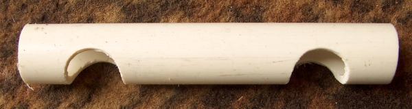
A finished spacer before installation.

The jig was fabricated from two scrap lengths of 2 x 4. After drilling a hole the diameter of the PVC pipe lengthways through one of the 2 x 4 sections, it was then sawed in half lengthways to make two "C" shaped blocks. One of these "C" blocks was screwed tightly to the lower, uncut 2 x 4 block. The other "C" block was screwed slightly loosely to the lower block. The spacing was adjusted so that I could put two sections of PVC pipe in between the two sections.
To use the jig, I placed two lengths of PVC pipe side by side between the "C" blocks and used a "C" clamp to squeeze the blocks tightly together so that the pipe sections could not rotate inside the "C" blocks.

A top view of the drilling jig after drilling two spacer tubes. Be careful with power tools! Clamp things down firmly and use safety glasses.

Moving right along, let's go to the top of the antenna, here shown laying on the ground.
Notice the bulge in the loop coaxes at the center mast. These bulges are where the shield of the coax cables has been cut completely through. This is necessary to prevent forming a short circuited turn, since the coax shield ends of the turns is connected together at the lower junction box. I cut out a 1/2 inch length of the cable's outer jacket and metal shield. Do this carefully, as the cable is soft and it is easy to damage it.
Of course, cutting through the shield of the coax mechanically weakens the coax considerably. To prevent the loop from collapsing, I cut a 10 inch length of 1/2 inch PVC pipe for each loop turn. I cut each pipe in half lengthways so that the halves could be fitted over the cut-out shield area of each cable.
Before I put the split pipe in place on the cable, I carefully cleaned the cut area and covered it with PVC cement to keep moisture out. Then I wrapped it with a few turns of PVC electrical tape and then put the split pipe over the cut area. I used a screw clamp to hold the two halves of the pipe together while I applied a double wrap of PVC electrical tape over the pipe. After this was done, I applied PVC cement over the tape.

That pretty much completes the mechanical part of the construction, so now we have to tune to loop to the desired frequency. To do this, I decided to build a binary switch bank of fourteen steps each step being double the value of the next lower one. Obviously, I needed fourteen switches. I had on hand a lot of old computer power supplies, so I liberated the 115/230 volt selector switches from fourteen of the power supplies. it turns out, these switches are almost ideal for this use.
Inspection (A.K.A., hit it with a hammer 'till it shatters) showed that these switches have heavy duty self-cleaning silver plated contacts, lubricated with what appears to be a pretty good grade of water resistant grease. The ON resistance is very low, which is just what we need for high Q antenna circuitry. I found that I could easily mount seven of these switches on either side of an electrical junction box extension unit. I used the original screws that held the switches in the power supplies to mount them in the junction box.

One end of each of the tuning capacitors are soldered to one side of the switch contacts and the other end connects to the common buss visible in the center of the photo. The other side of all the switches are connected together with a buss ring (actually square, in this case). Mica capacitors are used for most of the small value capacitance steps, and film capacitors are used for the larger steps. All the capacitors were chosen by testing them for loss and measuring their value. After the assembly was complete, the step values were tested again to check for damaged capacitors or wiring errors.

Here, you can see that the open ends of the loop have been bent to the correct position to meet the capacitor buss wires in preparation for final soldering into the circuit. Note the soldered extension on the left hand wire. Not also the long solder joint on the upper loop wire where it passes through the transformer. Hopefully that will be low enough resistance so as not to affect the circuit Q.

If you look carefully, you can see the loop end wires touching the buss wires from the capacitors. These will be soldered in place. Note also the black gasket about an inch in from the front of the extension assembly. That is the weather gasket between the extension assembly and the junction box - it's most important!

Soldering completed! The capacitor tuning bank is connected to the loop. All it needs is the cover plate and the feedline.

And here's the cover plate and the feedline. Note the very high-tech bubble-wrap-and-plastic-tape cover! Strange as it may seem, it actually works quite well. The day after I installed this (temporarily, of course) we had two inches of rain and lots of wind. Not a drop of water made it into the box. However, I will replace the cover with a sealed metal cover to make sure any RF and rain stays where they are supposed to be.

The base of the loop and the feedline connected and ready for use.

At the upper right of this picture, you can see the lower insulator for the vertical transmitting antenna for WC2XSR/13 The antenna tuner for the transmitting antenna is mounted against the tower, and is located just under the white cover at the lower center of the picture. In the background is the shielded loop antenna, which is only 25 feet away from the vertical transmitting antenna. With this setup, I can receive on 185.3 KHz while transmitting on 166.5 KHz at 400 watts.
Copyright (c) 2004 by Ralph M. Hartwell II, All rights reserved.
[ Home]