The "TEXAS Tube" - a Man-Sized Rife/Bare Tube
To my knowledge, this is the Largest Rife/Bare tube in the world!!
This unique tube was custom manufactured under Special License by Bill Cheb .
October 10, 2000
Updated November 15, 2000
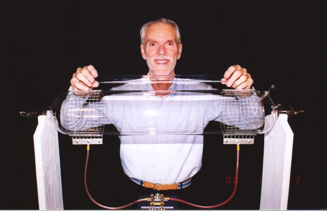
Shown here is the mighty TEXAS TUBE!
For comparison, I am holding a standard 18 inch long x 1 inch diameter Quartz Rife/Bare tube manufactured by Bill Cheb.
Recently I was given the opportunity to do a preliminary evaluation on a rather large Rife/Bare tube prior to its delivery to its new owner. When I say rather large I mean LARGE, as in TEXAS SIZE!
This custom manufactured product of the glass blowers art measures a whopping 6 inches in diameter, and is 3 feet long! It weighs 6 pounds, and it encloses nearly 60 times the volume of a standard Rife/Bare tube of 1 inch diameter and 18 inches length. The internal disk electrodes measure 1.5 inches in diameter. The tube is also equipped with an internal getter to maintain the gas purity during high power operation. Who knows what interesting effects will be discovered when using a tube with this much free internal ionization volume.
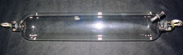
The TEXAS TUBE, manufactured by Bill Cheb .
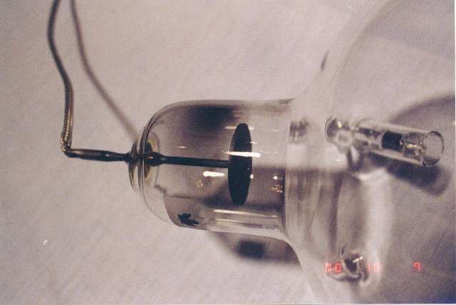
Here is the tube as it looked when I unpacked it upon arrival. A truly beautiful job! Notice that the tube as heavy braided leads attached to the internal electrodes. Visible on the upper right end of the tube is the special getter assembly installed by Bill Cheb. This ensures that the gas mixture in the tube will remain uncontaminated during high power operation.
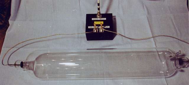
Here the tube is shown set up for testing using the internal electrodes of the tube. The RF power will be applied to the internal electrodes of the tube through a redesigned version of my Twisted Transmission Line (TTL) Balun.
INITIAL TESTS USING 60 Hz AC
As soon as the tube arrived, I set it up to run some tests on it. The first test I ran was to operate the tube from a neon sign transformer so that I could measure the operating voltage of the tube. Measurements indicated a rather low running potential of 750 volts AC. This reading would seem to indicate that this tube should be very easy to light up when driven by RF energy. In fact, this did indeed prove to be true as later tests showed.
Voltage tests indicated that when the tube was excited using the internal electrodes, the tube would fire when the applied voltage was about 2500, and the running voltage across the tube stabilized in the vicinity of 700 to 750 volts. This low starting voltage requirement meant that the design of the RF feed system should be easier since very high RF starting voltages would not be required. Previous tests have shown that using the internal electrodes in a tube makes RF matching much easier.
The downside of driving the tube through the internal electrodes is that the electrodes get extremely hot, and the tube may easily be damaged if the electrodes overheat badly. At the least, the gas in the tube will be contaminated if the electrode outgasses due to excessive heating, and at worst, the glass-to-metal electrode stem seal may fail due to overheating caused by the electrode.
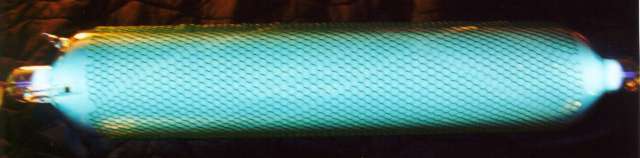
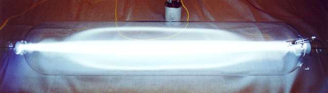
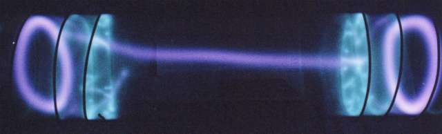
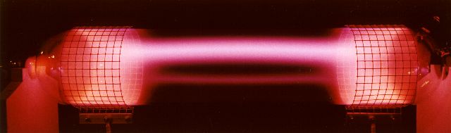
>Here the TEXAS Tube is shown being operated with 60 HZ AC power from a neon sign transformer. Note that the discharge evenly fills the entire gas volume of the tube. This is NOT the case when the tube is operated with RF power. (Visible on the TEXAS Tube is the removable plastic protective screening used for shipping and handling the tube.)
Oh, how pretty! When using AC power, the entire surface of the electrode, front and rear, is covered with a brilliant blue light. The remainder of the tube is filled with an Aqua colored cloud of luminosity.
INITIAL TESTS USING DC
Just for fun, I decided to test the tube on a DC power source. Most people never have a chance to see what a gas discharge tube looks like when operated on DC power. The visual appearance is quite striking, and quite unlike the appearance when running on AC power. The difference between the discharge at each electrode is shown in the photographs below.
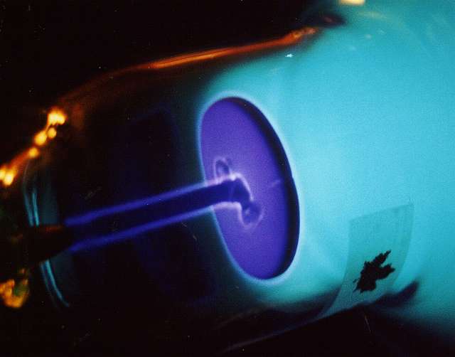
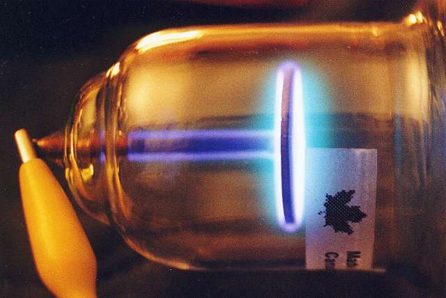
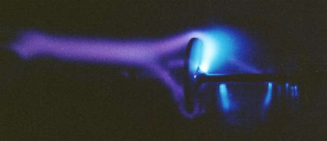
This picture shown the Positive electrode (Anode) and the strong glow discharge (called the Positive Column) connecting to the Anode. The Positive Column extends continuously from the Anode across the tube but stops short of reaching the Negative electrode (Cathode).
Here is a close up view of the Anode. Note that the Positive Column stops at the face of the Anode, and does not extend to the rear of the Anode structure.
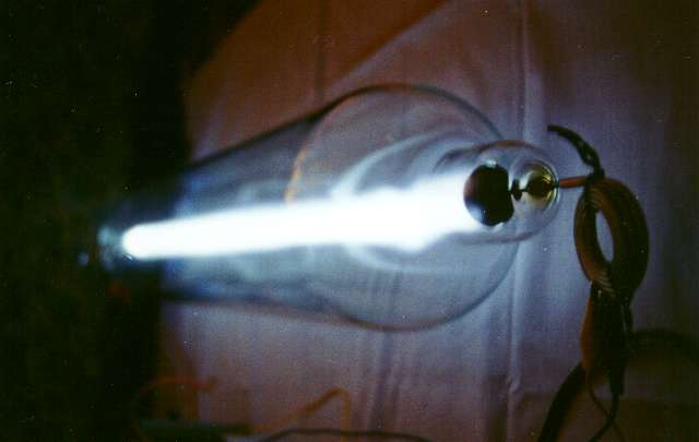
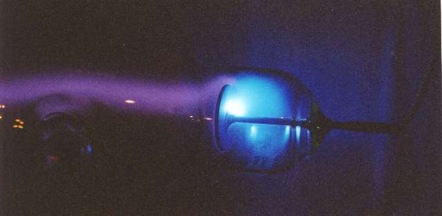
Here's a picture of the Cathode in operation. Wow!! It's really bright!! A brilliant deep Blue-Violet glow covers both the front and back of the entire Cathode, and even covers the lead-in support. Those electrons want to get away from the Cathode any way they can! Notice the dark space between the left end of the Positive Column and the Cathode Glow region. It's real - there's no visible discharge there. Crookes noted this dark region and wrote about it. Even though it is a dark region, electrons are steadily flowing through it to the Anode. When a gas discharge tube is operated on AC power, the electrodes switch polarity twice for each AC cycle, so you never get the chance to see the Cathode Glow, the Dark Space, and the Positive Column. Everything blurs into a steady light from the tube.
Here's an extreme close-up picture of the Cathode Glow. This picture does not do justice to the intense Blue-Violet color of the discharge. The orange color of the tube glass is due to the color of the light in the lab when this picture was taken.
Pulse Discharge Tests
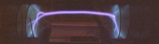
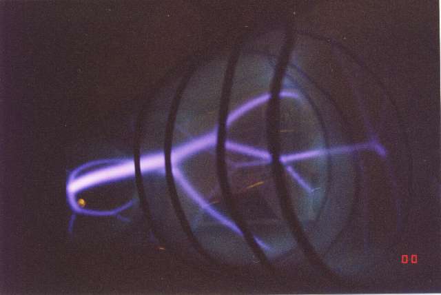
I thought it would be interesting to see how the TEXAS Tube would handle high power pulse discharges. Here you see a pulse discharge test. The tube is being subjected to a series of repetitive 10 Joule DC pulses, repeated about 8 times per second. The discharge appears as a laser-straight blinding bar of light.
This much energy applied all at once puts the gas inside the tube into the arc discharge region. During the pulse, the resistance of the gas column in the tube drops to just a few Ohms. The arc column discharge current approaches several hundred Amperes, and the peak power input to the tube may approach 10KW during each pulse. The average power input to the tube is only a few dozen watts, so no serious heating of the tube takes place during the test.
The curved "bow" sections above and below the center of the discharge are internal reflections of the discharge column from the back wall of the TEXAS Tube. The actual discharge looks like a Light Sabre in action! And, it is as bright as it looks - in fact, even brighter! It's painful to look at if viewed at close range.
And, the tube is NOISY! It literally rings with acoustic energy, and generates quite a loud audio signal through the air. It can literally be heard 50 feet away. For a sample of the sound recorded during these pulse tests, click HERE to download a zipped MP3 audio file of the Sounds of the TEXAS Tube.
Looking at the tube at an angle shows the straightness of the pulse test plasma discharge column. This is typical of high current, short pulse discharges send through rarified gasses. The gas is heated to a high temperature during the pulse, but because of the brief pulse length, the heated gas does not have enough time to rise to the top of the tube during each pulse. For this reason, the discharge remains fairly straight across the length of the tube.
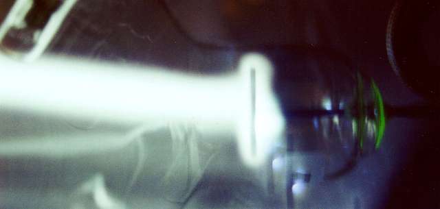
Here is a close-up view of one of the electrodes during a series of 10 Joule pulses. The brightness of the discharge is like looking at the sun! Note the green glow on the extreme right end of the tube. This is caused by intense Blue and Ultraviolet light from the discharge. This light causes the glass by the electrode lead-in seal to fluoresce brilliantly.
RF TESTS #1 - USING INTERNAL ELECTRODES
After the initial tests described above, it was time to connect the TEXAS Tube to what it was really designed for, a high powered Rife/Bare system.
For the following tests, I used my basic test system, consisting of a modified Yaesu-Munsen FLdx-400 transmitter, followed by a Heath HA-10 Warrior RF power amplifier, capable of generating more than 750 watts of RF power at 27.10 MHz. The output of the HA-10 goes through a Palomar M-827 VSWR meter, and then on to a Heath SA-2060 kilowatt rated antenna tuner.
Following the tuner, a length of RG8A/U coaxial cable connects to a specially built version of my Twisted Transmission Line Balun matching system. Here is an Internal Viewof the TTL. The output of the TTL system connects directly to the tubes internal electrodes, or to spiral wound external electrodes, which were used in later tests.
The audio modulating frequency control was supplied by a Heath switchable audio oscillator, model IG-5218. A Fordham 550 MHz frequency counter was used to monitor the frequency. Since these tests were to characterize the RF induced discharge and not specifically test for physical results, extreme frequency accuracy was not required.
The modulating waveform was adjustable from a 50% square wave down to a 6.5 microsecond "on time" pulse per modulation cycle. RF power to the tube was continuously variable from approximately 100 watts to 750 watts.
FIRST LIGHT !
The following set of tests were run with the RF power applied directly to the internal electrodes of the tube. It was hoped that since this was a large tube with big electrodes, high power could be fed directly to the internal electrodes, thereby simplifying the RF feed system considerably. As it turned out, this was not entirely the case.
In the tests shown below, the tube was mounted about 4 inches above a grounded metal plate.
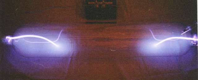
When RF power was first applied, a luminous blue haze enveloped the electrodes. As the power was increased, a tongue of brilliant violet light leaped out from each electrode and searched for the center of the tube. Because the tube was laying on a grounded plate, the RF electric field between the electrodes was distorted towards the metal plate, and the discharge quickly headed for the grounded metal plate.
This photo was taken with with the RF peak power set to about 90 watts output, the average RF power output was about 45 watts. The modulation duty cycle was set for 50% (symmetrical square wave), and a modulating frequency of 1000 Hz was used.
This is the discharge from the right electrode heading for the tube wall and the grounded plate beneath the tube. Note that the discharge from the electrode occurs from both the front and the rear of the electrode, and joins together in front of the electrode. Note, too, the "beading" effect of the discharge close to the electrode. This effect is commonly seen when the RF energy intensity in not sufficient to allow complete ionization of the gas in the path of the discharge.
Why do these glowing beads form? One theory is that prior to the ionization of the gas, the electric field if fairly uniform in three dimensions. A soon as the discharge occurs, the local electric field inside the glowing gas drops to a lower level due to the energy being used to maintain the ionized state.
This local field reduction causes the electric field surrounding the ionized region to be warped towards the ionized region. This warping has two effects; first, it supplies additional energy to maintain the ionization where it has already begun, and, second, it reduces the RF energy in the non-ionized regions to a level too low to allow ionization to begin there. The result is a series of ionized and non-ionized regions occurring adjacent to each other.
Once this beading effect occurs, it will maintain itself in a stable condition unless influenced by outside conditions; external magnetic fields, RF power level changes, "hand capacity" caused by moving grounded or radio frequency reflecting objects, such as your hand, near the tube.

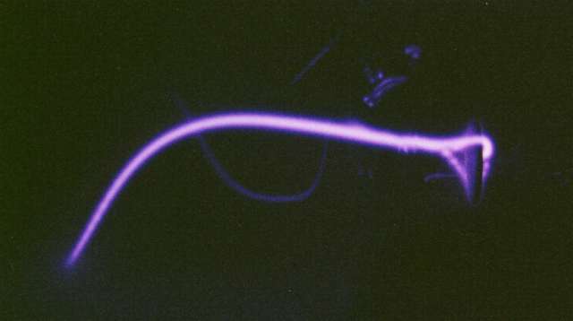
Here's the same type of discharge as seen from the opposite electrode. (The "U" shaped squiggle is a reflection of the main discharge on the back wall of the tube.)
Note that the discharge curves first up, then dives down to meet the grounded plate. The upward curve is because the ionized gas is HOT and wants to rise to the top of the tube, just as hot smoke rises from a fire. Unlike the case in the pulse tests, this discharge is on for a much long period of time. This allows the plasma column to heat up enough to rise towards the top of the tube. In small diameter tubes, this effect is almost never seen since in a small diameter tube, the plasma column cannot move very far before it encounters the cooler tube wall. As soon as the hot plasma encounters the tube wall, it cools off and the discharge tends to move back towards the center of the tube.
This picture shows the upward rise of the discharge column. In this picture, the tube is being operated at a peak RF power of 700 watts and an average power of about 350 watts. The discharge is hard against the top of the tube, and quickly heats the top of the tube when in operation.
Rolling the tube back and forth while it is in operation results in the discharge column first following the tube as you roll it, then it slowly swings back to the top of the tube again as you stop rolling the tube. It reminds you of a very flexible floating balloon drifting back and forth. Picking up the tube and quickly twisting it sideways back and forth causes the discharge to whip all around the tube and twist into interesting shapes. (Don't choke on your coffee, Bill, I was VERY careful not to drop the tube or hit anything with it.) <G>
Notice the intense bright Blue discharge behind the electrodes. (actually Blue-Violet, but the camera does not record the intense color.) As the RF power is increased, the discharge tends to want to initiate itself from behind the electrodes instead of in front of them.
Shown here is the discharge column wandering back and forth across the top of the tube. An very interesting visual effect!
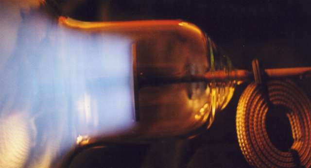
Look at this - the RF discharge starts where the electrode lead-in connects to the back of the electrode. The discharge then goes around the edge of the electrode and then continues on to the discharge column. This photo was taken with the TEXAS TUBE running at a peak power level of 700 watts and a pulse width of 100 microseconds.
For this photograph, the tube was operated at 700 watts peak power, and 350 watts average power, symmetrical square wave modulated. The camera was stopped down so as to bring out the details of the very intense discharge occurring behind the electrode. Visual observation shows that a spot on the electrode actually becomes almost white hot and begins to vaporize. This vaporized (sputtered) material quickly deposits itself on the wall of the tube near the electrode and causes a silvery coating to appear on the tube inner wall.
This is a close up view of the electrode sputtering caused by high power RF operation using the internal electrodes of the tube. This sputtering was caused in less than three minutes of operation at 700 watts peak and 350 watts average power to the tube. It is apparent that the use of internal electrodes severely limits the usable power of this magnificent tube.
When driving the electrodes directly, it is recommended that an external finned heat sink be attached to each electrode feed through post to help cool the glass to metal seal and prevent tube wall fracture at the electrode feed through point.
RF TESTS #2 - USING SPIRAL WRAPPED EXTERNAL ELECTRODES
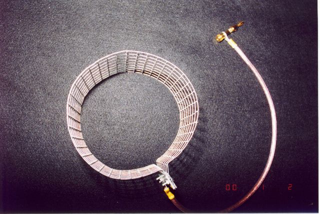
The following series of pictures shows the visual results of testing while using a set of spiral wrapped external electrodes near the ends of the tube. This allowed much more RF power to be applied to the tube without damaging the electrodes or overheating the tube. Experience with other Rife/Bare tubes has shown that a much higher RF power level may be sent to the tube when using external electrodes. One of the easiest external electrodes to build is the simple spirally wrapped insulated wire electrode. For these tests, the wire used is #12 AWG solid copper wire which has a covering of THHN plastic insulation 15 mils in thickness. Each turn of the spiral electrodes is spaced about one inch apart. There are four turns in each electrode.
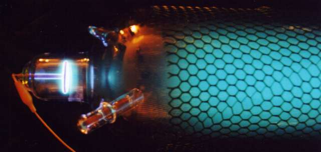
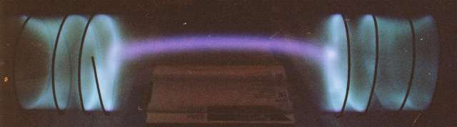
Here the tube is being operated at 250 Watts Peak Power, 12.7 watts Average Power, with a Modulation Frequency 10,000 HZ, and a 6.5 Microsecond Pulse Width. What an interesting display! Note that the discharge still wants to rise to the top of the tube. Also note the interesting forked discharge at the ends of the tube where the discharge column encounters the spiral external electrodes.
A Close-up View of the Bifurcated Discharge, Looking Through the Spiral External Electrode. Also note the slight beading effect in the lower powered branches of the discharge.
Here is the tube while running at 700 Watts Peak Power, 4.5 watts Average Power, Modulation Frequency 1,000 HZ, with a 6.5 Microsecond Pulse Width.
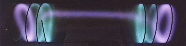
In this photograph, the tube is being operated at 700 Watts Peak Power, 45.5 watts Average Power, Modulation Frequency 10,000 HZ, and a 6.5 Microsecond Pulse Width. Notice the intriguing separation of colors in the discharge regions inside the electrodes.
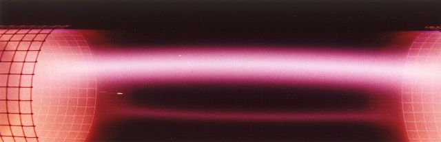
Here the tube is running at 700 Watts Peak Power, 350 Watts Average Power, Modulation Frequency 1,000 HZ Square Wave. Note that the intensity of the discharge column has increased. The gas column has more continuous "on" time during each modulation cycle to heat up and head for the top of the tube. The bright spot in the top of the plasma column is a reflection from the back wall of the tube, and is not part of the discharge.
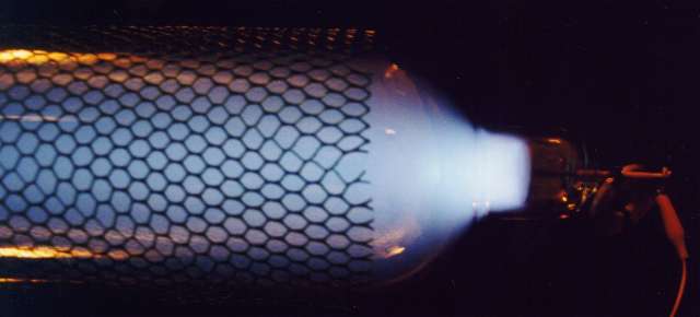
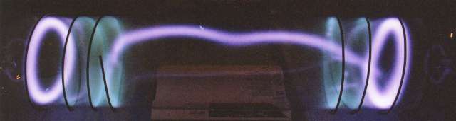
Here's a photograph of the tube running at the maximum available power of 750 Watts Continuous Wave RF Power, with no Modulation. The camera has automatically adjusted the exposure to compensate for the increased brightness of the plasma. Notice that the discharge nearest the inside ends of the external electrodes has greatly increased, taking on a "flame" appearance. Wow!
What causes this beautiful halo-like display? It was discovered that the spiral electrodes on this giant tube are large enough so that there is an RF phase shift along the length of each spiral. That is, they behave much like a tuned circuit, rather than simply as a metal electrode. This causes the RF field to change polarity and amplitude from one end of the spiral wrap to the other end. This creates a powerful reversal of the electric field potential inside of each electrode spiral, and that in turn causes the discharge to assume this most unusual shape.
Even after 10 minutes of operating at this high power level, you can still place your hands on the tube without getting burnt. This tube can handle some REAL POWER!! Let's try some other tests...
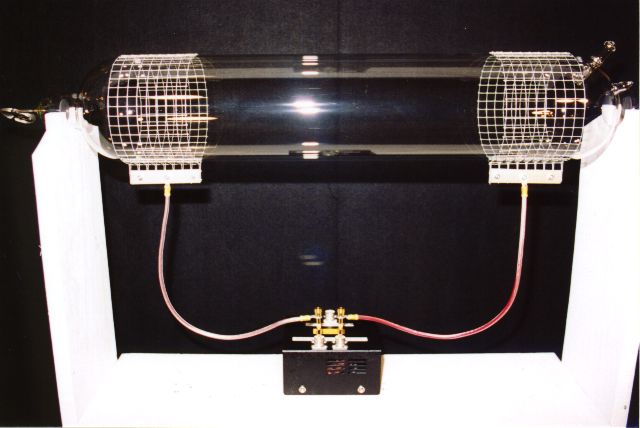
It is known that much higher RF power levels may be used with Rife/Bare plasma tubes when using external electrodes. Since this is a true TEXAS TUBE, we want to be able to send as much power to this baby as possible! To that end, I decided to fit the tube with a set of external collar-style electrodes. Before I show you the results of these tests, please take a look at my test setup.
Before continuing with the RF testing, I felt that the TEXAS TUBE should have a suitable holder. I constructed a simple but sturdy stand from some 1 x 8 planks. I included a wooden shelf below the tube so that the Twisted Transmission Line Balun could be placed there. The stand is simply made, and has a semi-circular cut out at the top of each end support which holds the TEXAS TUBE securely positioned for testing. Since the tube simply lays in the mounting, there is little, if any, mechanical stress on the tube due to thermal expansion and contraction during testing. This is what the tube looks like sitting in the holder:
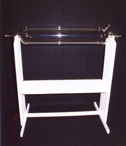
The holder for the TEXAS TUBE measures 32 inches wide and 32 inches high. An equipment shelf is mounted 18 inches below the center line of the tube. A pair of 26 inch lengths of 1" x 2" board are used as feet for stability of the holder. The end supports are made of 1" x 8" boards, and the shelf is a piece of 3/4" x 12" plywood. Heavy metal screws are used for assembly, and the unit is painted white.
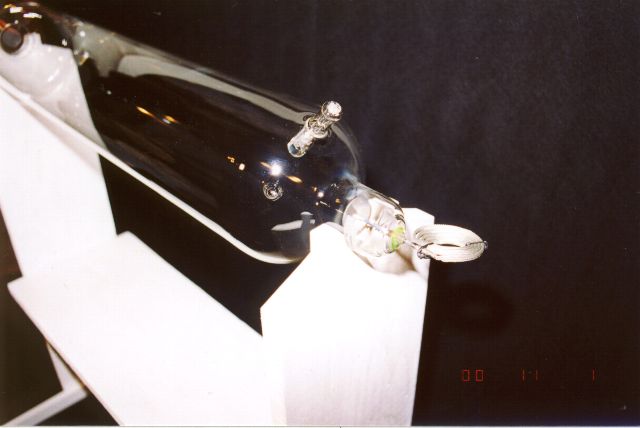
This is a view of the tube showing the position of the internal getter in relation to the end electrode. Notice the braided lead-in wire attached to the electrode feed through post. It is still coiled up as it was during shipment. I left it that way since it is not used during tests with the external electrodes.
This picture also shows the semi-circular cut out in the wooden end post which holds the TEXAS TUBE in place during operation. If desired, an elastic strap may be placed over the top of the tube and fastened to the wooden tube holder. This is not really necessary since the tube is heavy and stays in place quite well.
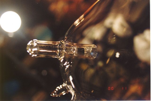
A close-up view of the internal getter assembly. The getter adsorbs unwanted gasses which may be released into the tube during extended periods of high power operation. This maintains the purity of the gas fill in the TEXAS TUBE under just about all operating conditions.
In this picture, you see the TEXAS TUBE fitted out with its brand-new set of external wire mesh electrodes. They are constructed of steel wire which are coated with Zinc. This mesh wire is commonly called "Hardware Cloth." The spacing between adjacent wires in the mesh is 1/2 inch or ~ 12.5 mm. Each electrode is 4 inches wide. They may be slid along the length of the tube and allow the researcher to easily adjust the spacing between the electrodes during operation.
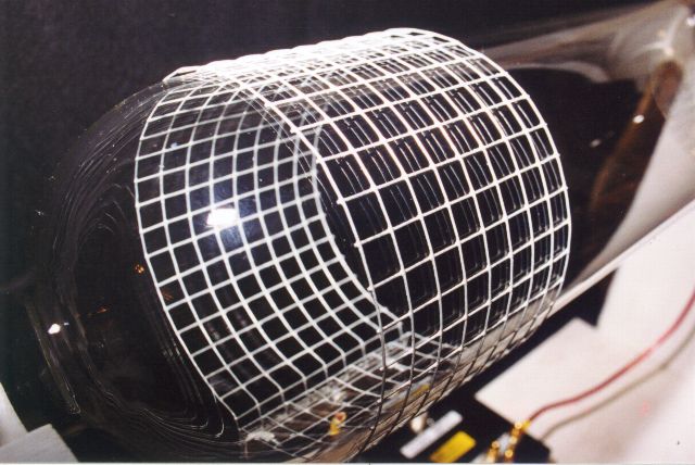
An oblique view of one of the mesh collar electrodes installed on the TEXAS TUBE. At the operating frequency of 27.12 MHz, the open mesh acts as though it were a solid metal sheet. The open design allows for better cooling of the tube wall. The open construction also allows light to escape from the tube which would normally be blocked if the electrodes were actually constructed from a solid metal sheet.
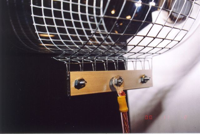
This picture shows the aluminum strips which are used to clamp the open ends of the mesh electrode together. There is one metal strip on either side of the electrode ends. The strips are fastened together with 6-32 hardware, and the lead from the Balun connects to the center bolt.
What's the big deal with Collar Electrodes anyway? Well, there are several reasons that Collar Electrodes work better than spiral electrodes. A spiral electrode, although quick and easy to build, has a considerable amount of self-inductance since it is simply a coil of wire. At the usual Rife/Bare carrier frequency of 27.12 MHz, this self-inductance can cause serious distortions of the RF electric field distribution inside the tube.
As the plasma discharge grows stronger or weaker, it changes the effective capacitance between the plasma cloud and the spiral electrode. This can cause the tuning of the system to vary well beyond expected values. This can cause unexpected discontinuities in tuning and unstable operation of the tube due to an unstable plasma discharge as the power levels are changed. In moderate cases, the result may be seen as the need to constantly change the adjustment of the antenna tuner as the RF power level to the tube is changed or when the audio modulation frequency changes. In severe cases, it may even cause RF power amplifier failure
A Mesh electrode, on the other hand, behaves electrically as though it were made of a solid metal sheet, and appear to the system as though it is simply a capacitor. The self-inductance of the collar electrode is also very low, because it is not a spiral. This lack of self-inductance of the electrode means that the detuning effect of the changing plasma coupling to the electrodes is greatly minimized. This provides a more uniform and much more intense RF electric field inside the tube. This field generates a strong plasma glow when the tube is in operation. It also allows the tube to operate with much lower power levels than commonly seen with Rife/Bare tubes.
Here you are looking through the mesh electrode, on the axis of the plasma column. Here you can see how the ends of the hardware cloth have been bent at right angles to the tube wall. You can also see the clamping straps and clamp hardware. Notice the slight "V" shape in the hardware cloth where the ends are clamped together. When the electrode is slipped over the tube, the "V" acts as a spring as the electrode is forced open slightly to accommodate the tube. This keeps the mesh electrode held tightly against the tube wall, but allows for thermal expansion when the tube heats up during operation.
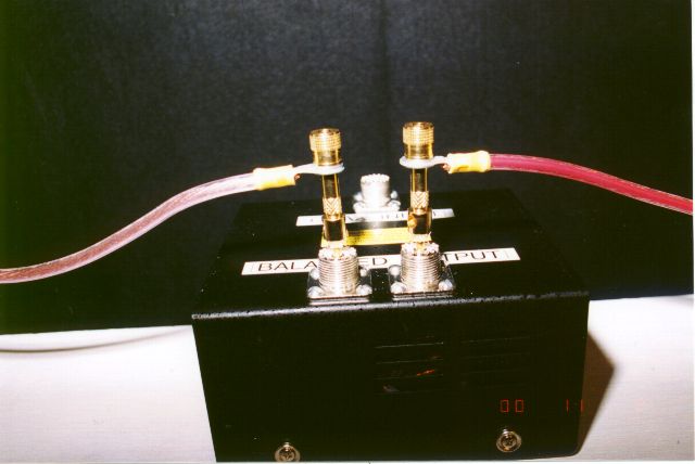
The tube electrodes are connected to the Twisted Transmission Line Balun (shown here) with short lengths of 12 gauge stranded speaker wire available from Radio Shack. The TTL Balun is enclosed in a ventilated metal project box, also available at Radio Shack. The Balun input and output connections are made through standard SO-239 coaxial cable chassis mount connectors. Although coaxial cable is not used for the output connections to the Balun, SO-239 connectors make handy connectors, as they handle several thousand volts fairly well, and will accept both PL-259 coax plugs and standard Banana Plug pins which are being used here.
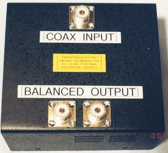
A close up of the modified Twisted Transmission Line Balun. SO-239 connectors are used for mounting the actual TTL inside the enclosure as well as providing convenient connections for testing.
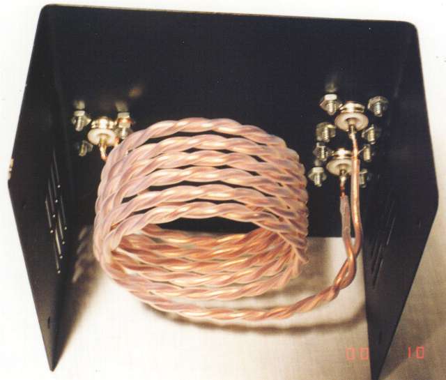
Interior view of the modified TTL Balun assembly. The input connection (coming from the antenna tuner) is on the left of the picture. The output connections which go to the Rife/Bare tube are visible on the right side of the enclosure. The Balun coil is supports itself, and is connected mechanically only to the coax connectors. The Balun coil itself is constructed of two 76 inch lengths of Teflon covered #12 solid copper wire. The wires are twisted together 2 turns per inch and the spiral coils are separated from each other by about 1/8 inch. The design frequency for the Balun is 27.120 MHz.
RF TESTS #3 - USING EXTERNAL MESH COLLAR ELECTRODES
Power up!! This pretty little plasma ball is the result of sending a rather puny 10 watts - that's right, just 10 watts - to the TEXAS TUBE.
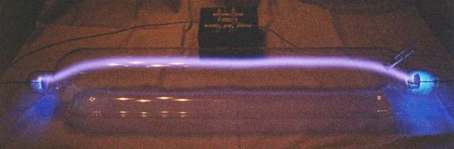
In this picture, the electrodes have been moved quite close together. In fact, they are almost touching each other, as you will see if you look carefully at the picture. Note the slight gap, slightly less than 1/4 of an inch, between the electrodes. The glow appears visually very uniform throughout the volume of the tube enclosed by the electrodes, indicating that the RF field produced by the electrodes is quite uniform across the tube. This is what we want to obtain good power transfer to the tube and stable operation. The color of the discharge is a deep Red-Orange, with just a faint touch of Blue near the center.
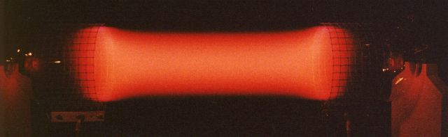
In this picture, the RF power applied to the tube has been raised to about 100 watts and the electrodes have been moved back to their normal position near the ends of the tube. At this power level, the discharge appears as a luminous, transparent fog which completely fills the inside of the tube from wall to wall. It is brightest directly inside of the electrodes where the RF field is the strongest.
Notice the slight pinching or "waist" effect visible in the plasma column. In part, this is a visual artifact due to the slightly lower brightness of the plasma column in the space between the electrodes and partly because the discharge wants to concentrate itself into the most efficient path possible.
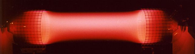
Increasing the RF power to 200 watts makes the plasma column become quite a bit brighter. Something else begins to happen in the tube at this point. The plasma discharge begins concentrating itself into a bright central core.
What is happening here is that the electric field is the strongest in the center of the tube, so the most current tends to flow through the ionized gas in that region of the tube. The higher the applied RF power, the more the gas becomes ionized. This increase in ionization causes that part of the gas column to become more conductive, which causes more current to flow through that part of the tube. This, in turn causes even more ionization of the gas, which again increases the current. This process indicates that the tube possesses a "negative resistance" characteristic.
This does NOT mean that the electrical resistance of the gas column is really a negative value, but means that if you send MORE current through the resistance of the ionized gas, the voltage drop across the gas column DECREASES. If you inserted a normal resistor having a "positive resistance" in the circuit, you would find that increasing the current through the resistor would cause an INCREASED voltage to appear across the resistor. Since the decrease in voltage across the tube with increasing current through the tube is the reverse of what we would see if we used a normal resistor, we call the effect Negative Resistance.
What does this mean for a Rife/Bare tube? It means that the more power we send to the tube the "tighter" and more compressed the plasma column will become. This is normal for any high power discharge through a rarified gas tube. We are able to see this effect very plainly in the TEXAS TUBE since it has such a large diameter. In smaller tubes, the effect is hidden because the inner diameter of the tube is usually smaller than what the diameter of the ionized gas column would be if it were free to set its own size. In the TEXAS TUBE, the column can be six inches across if it wants to be!!
An extreme example was shown earlier in this article where I showed DC Pulse tests of the tube. In those tests, the peak power level was much higher than was used in the tests shown here. In the Pulse Test pictures, you can plainly see the plasma column is very small and tight, even though is is carrying several thousand times the power we are using here. The only way to light up a Rife/Bare tube wall-to-wall evenly is to use a low enough power level so that the tube does not switch into the concentrated discharge mode, or to use a small enough diameter tube so that the plasma column cannot try to shrink down to the diameter of the tube.
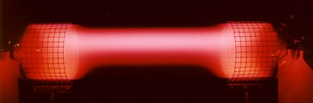
At the 300 watt power level the plasma column begins to show a well-defined concentration into a compressed beam. Note that much less of the total volume of the tube is filled with ionized gas. Much more of the available RF power is going into the main beam. Note, too, that the beam is starting to lift itself towards the top of the tube. The ionized gas is hot, and wants to rise, as any heated gas will do.
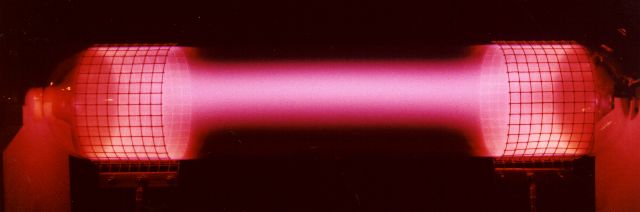
Power up to 500 watts!
Now we have a strong concentration in the main discharge channel. Even less of the rest of the tubes volume is lit up. The main channel is taking the bulk of the RF power. The brightness of the discharge is impressive. Note the change in color from the almost Neon Red-Orange color of the first faint glow at 10 and 100 watts to the violet color showing in the tube at this power level. The TEXAS TUBE is filled with Argon, but it shows colors and visual effects not readily seen with smaller tubes. A really impressive light show!!
It's quite a treat to set the system to 304 Hz and just let it run and sit back and enjoy the color and feel of the TEXAS TUBE.
750 Scorching Watts!
This is a real test of not only the TEXAS TUBE, but also of the RF power amplifier and the antenna tuner. At this power level, any mistuning will quickly melt coax cables, burn out antenna tuners or fracture ferrite Balun cores. (Been there; done all three; hated it all three times!) But with care, everything works right, and this picture shows how it looked.
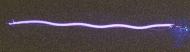
To bring out some of the detail of the very intense plasma beam, I reduced the camera exposure somewhat. It's obvious from this picture that at this high power level the main plasma channel is grabbing most of the power for itself. There is a strong central core in the plasma beam, which appears visually to be a brilliant Blue-Violet color. It is surrounded by a Violet-Red region, which fades to a Red-Pink haze and then on to invisibility. Note the reflection of the plasma beam. You can see it reflected from the back wall of the tube, just below the plasma beam.
This is a close-up picture of the 750 watt plasma channel. Note the strong central core where the power is concentrated. The beam shows a slight upward curve as the lifting effect of the hot gas fights against the tendency of the plasma beam to maintain the straightest path between the electrodes. This picture was taken at a distance of about 2 feet from the tube. At that range, it's like being punched in the gut when you hit the right frequency!!!
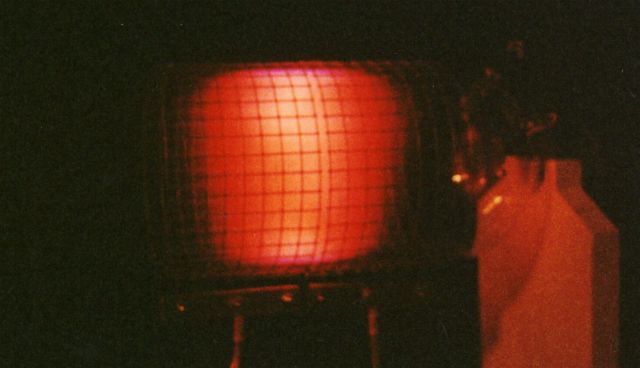
At this high power level, the light from the tube takes on an unusual two-edged hue. There's a very strong Red component, as well as a powerful Blue/Violet output. Exposed flesh appears as a light to medium leather brown color. The Blue/Violet light causes everything in the room which is blue or white to light up a brilliant blue. White cloth which has been washed using a detergent with a whitening agent fluoresces a brilliant blue white. Many plastics also glow in brilliant colors as well. The TV screen lights up when exposed to the Texas Tubes light. Tests show that there seems to be a moderate amount of Ultraviolet light emitted at this power level, but further testing will be needed to confirm this.
Summary, Conclusions and some Stray Thoughts...
Testing The TEXAS TUBE was an interesting experience. From an RF engineering standpoint, the huge internal volume of this tube makes testing it and the effects it produces much more akin to running tests in free space. In this tube, the plasma is free to go where it wants and so what it wants to do, unlike smaller tubes which confine and direct the plasma inside their much smaller volume. Acoustic effects are pronounced, and the tube "sings" nicely. The low starting voltage of the tube and the ability to ionize a large volume of plasma causes the tube to present a much more constant load to the antenna tuner. The VSWR readings are fairly low, running between 3.0:1 and 1.2:1, depending on tuning and the applied RF power. VSWR changes very little with changes in modulation frequency. Since the tube loads the antenna tuner better than smaller tubes do, the Balun (both ferrite core and Twisted Transmission Line types) exhibit far less heating under power. Heating of the coaxial cable is also greatly reduced, and changes in coax cable length between the antenna tuner and the Balun are more easily accommodated with less antenna tuner readjustment required. The tube starts on low power much better than smaller tubes seem to do.
How does the power handling capability of the TEXAS TUBE compare to a more standard Rife/Bare tube?
We must consider both the internal volume of the tube and the surface area of the tube. A large percentage of the RF power sent to a Rife/Bare plasma tube is converted into heat which heats the gas plasma. This heat must be removed from the tube by radiation (a small percentage) and by conduction through the walls of the tube (the larger percentage.)
The power the tube can handle is proportional to the volume of the tube but the heat dissipation which ultimately limits the maximum average power the tube can handle is proportional to the surface area of the tube.
In the case of the TEXAS TUBE as compared to an 18 inch x 1 inch Rife/Bare tube, we see that the volume of the TEXAS TUBE is 60 times that of the standard tube, but the surface area is only 10 times greater.
This means that while the maximum power we should be able to apply to the TEXAS TUBE is theoretically 60 times that which the standard Rife/Bare tube can take, we find that because of the limit imposed by the surface area of the TEXAS TUBE, we can actually only send a power level 10 times greater to the TEXAS TUBE without overheating the tube. This is not an insignificant amount of power, however.
Measuring RF Power Levels
Let's digress here for a moment, and discuss PEAK and AVERAGE power levels. First, let's assume that we have an RF carrier with no modulation which reads 100 watts on an RF wattmeter. This RF signal has a PEAK power of 100 watts, and an AVERAGE power of 100 watts.
Now, let's modulate that same 100 watt peak/average RF signal with a square wave which has a 50% duty cycle. (This means that the square wave will turn the RF carrier ON for 50% of the time, and turn it OFF for 50% of the time.)
Now we see (if we have the proper type wattmeter) that the PEAK power is still at 100 watts during the time the RF carrier is turned on. Obviously, the carrier level is zero when it is turned off. Since it is ON half the time and OFF half the time, the AVERAGE power is 100 / 2 = 50 watts. So, in this case, we have a PEAK power of 100 watts and an AVERAGE power of 50 watts available to drive our Rife/Bare tube.
Furthermore, if we are gating the modulated RF signal with a 4 Hz square wave which is also using a 50% duty cycle, we find that we once again reduce the AVERAGE RF power by an additional 50% dropping it down to just 25 watts average power while at the same time maintaining the PEAK power at 100 watts.
It is the average power which heats up your Rife/Bare tube. If your tube is able to handle 100 watts of AVERAGE power without failure, you will find that if you are modulating the wave with a 50% duty cycle square wave, you can now crank up the transmitter power to 200 watts PEAK power. This will raise the AVERAGE power back to the maximum level of 100 watts that your tube is able to handle. If you are modulating the RF carrier with a 50% duty cycle square wave, AND pulsing the carrier with a 4 Hz 50% duty cycle gate pulse, you can double the transmitter power again, to a peak power level of 400 watts while still sending only 100 watts average power to your Rife/Bare tube.
So, What can The TEXAS TUBE Really Handle?
Since a typical well constructed Rife/Bare tube of 1 inch diameter by 18-20 inches long operating on an unmodulated RF signal can handle close to 150 watts average power on a continuous basis without failure, 10 times that amount is 1,500 watts average power. That is a LOT of POWER!
NOTE: Since the hot plasma will tend to heat the top portion of the TEXAS TUBE more than the bottom of the tube, I would suggest reducing this maximum value to something less until temperature measurements have been taken to ensure the safety of the tube. In the meantime, let's continue on at FULL POWER!
If you are modulating the RF carrier with a 50% duty cycle square wave, you can crank your amplifier up to 3,000 watts peak (1,500 watts average).
If you are modulating the RF carrier with a 50% duty cycle square wave, AND pulsing the carrier with a 4 Hz 50% duty cycle gate pulse, you can crank up the power level of your amplifier once more to a stunning level of 6,000 watts peak power (1,500 watts average).
WOW !
Yet to be posted on this page - Data on RF field measurements, pictures of optical waveforms from The TEXAS TUBE, and a discussion of internal tube electrodes and the power levels they can handle.
Updates will be posted to this page as time permits. Please check the Update Line at the top of this web page for the latest update.
Out of the Darkness, Into the Light!
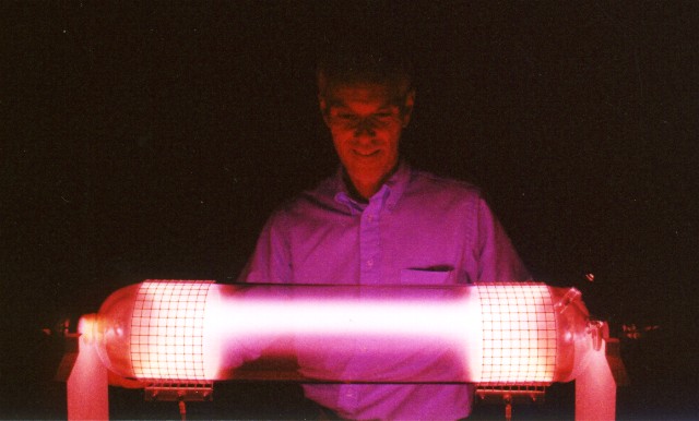
The author, Ralph Hartwell, inspecting the TEXAS TUBE at very close range during high power testing.
[ Home ]