Build yourself an RF Ammeter
by W5JGV
An Easy way to Monitor RF, AC or DC current with one Instrument
While I was working on my 166.5 KC transmitter, needed to be able to read the RF drive to the final PA stage. To do this required an RF ammeter that could read down to 100 ma with reasonable accuracy. A search of my Junque Box came up empty, and the great floating Hamfest, eBay, didn't offer any hope either. I decided the time had come to make my own RF ammeter. As it turned out, this was a 30 minute project.
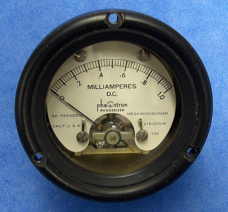
First, I needed a suitable meter. My recent search of my Junque Box had uncovered a likely candidate for conversion as seen below.
Well, the meter range is about right - the reading of 100 ma that I need to see is easily readable, and the full scale reading of 1 ampere would make the meter usable for testing with higher powered gear. But, since the DC meter cannot read RF, what to do?
Simple! Just grab an old computer power supply and rob a few parts from that!
What I did was remove four small 1 ampere Schottky rectifier diodes from the computer power supply circuit board and connect them in a full wave bridge rectifier configuration directly on the terminals of the meter. The (+) and (-) terminals of the meter are then connected directly to the (+) and (-) outputs of the bridge rectifier. The other two bridge rectifier connections, (shown as home-made ring terminals in this picture,) are the RF input connections to the bridge rectifier.
Since the meter only reads 1 mA full scale, and I wanted to be able to read 1 A full scale, I placed a non-inductive shunt resistor of 0.1 Ohms resistance directly across the meter (+) and (-) terminals to bypass the other 999 mA of current.

The incoming RF current is rectified by the Schottky diodes and is converted to pulsating DC. 999/1000 ths of the DC passes through the meter shunt resistor, and the remaining 1/1000 of the DC passes through the meter. This causes the pointer of the meter to deflect in proportion to the applied RF current. Because the pulsating DC is at a high frequency, there is no visible "bobble" of the meter's pointer during operation.
Calculating the shunt resistor value was done by first determining the internal resistance of the meter. In this case, it is 100 Ohms - which just happens to be shown on the front of the meter scale. Next, I determined the voltage that would have to be placed across the meter's resistance of 100 Ohms to cause a full scale deflection (1 mA).
so: E = I * R
or: E = .001 A * 100 Ohms
or: E = 0.1 V
So we need to have a resistor of such a value that when 1 Ampere (actually .999 A) flows through it, there will be 0.1 Volt dropped across the resistor.
Rounding off the current of 0.999 Ampere to 1 Ampere, and again using Ohms Law, we find that:
R = E / I
or: R = 0.1 V / 1 A
so: R = 0.1 Ohm
The power in Watts dissipated as heat across the shunt resistor at full scale current is:
W = I * E, where I is the current through the resistor, and E is the voltage drop across the resistor at that current.
In this case, W = 1 A * 0.1 V
so: W = 0.1 Watt, so a 1 watt resistor would give an excellent heating safety factor.
o - Note that because of the very low resistance of the shunt resistor, the resistor leads mush be short so that the lead resistance does not introduce measurement errors.
o - Schottky diodes are required because standard diodes are not fast enough to prevent reverse conduction losses at RF frequencies.
o - This instrument introduces a fixed voltage drop of about 0.4 volts across the combination of the meter and the diodes. This voltage drop is fairly constant for current values from about 0.01 to 1.0 A.
o - Because of the low forward voltage drop of the Schottky diodes, the meter reading is accurate down to about 0.02 Amperes, as long as the circuit under test can accept a voltage drop of about 0.4 volts. Using the Schottky diodes eliminates the need to linearize the meter readings or to draw a new scale for the RF ammeter. The same scale will apply to DC, AC, and RF readings.
o - The voltage rating of the diodes is not critical, because they will never see a large reverse voltage. The DC meter and shunt resistor appear as a virtual short circuit across the DC output from the bridge rectifier.
o - If a higher full scale value is required, the shunt resistor and / or the meter movement may be adjusted as needed. It will also be necessary to use Schottky diodes that are rated for the higher current.
o- Although it is not shown in the photograph, it is a good idea to place an RF bypass capacitor directly across the meter's DC terminals. This is suggested because as the RF frequency increases, the coil of the meter movement will exhibit a rising impedance to the rectified RF pulses, and will cause a drop in the apparent meter reading at higher frequencies. I found that a value between 0.01 and 0.2 uF works well. Use a low inductance capacitor, such as a Polypropylene capacitor, or any good RF rated capacitor.
.
73, Ralph W5JGV
[Home]
The entire contents of this web site are Copyright © 2002 - 2006 by Ralph M. Hartwell II, all rights reserved.