.jpg)
A 70 Foot Vertical Antenna from Aluminum Irrigation Pipe
- by W5JGV -
This is an ongoing project, so this page is still under construction.
Posted 30 July 2010
This antenna was built to replace my previous 67 foot vertical antenna which I built several years ago. It was made from two inch diameter thin wall aluminum pipe. It worked quite well, but unfortunately, I managed to knock it down about two weeks after I erected it. It seems there was an unfortunate conflict between one of the guy lines and my tractor... When I get the time, I'll post the story and pictures about that antenna. Erecting that antenna was "interesting," as they say. It was sort of like trying to make a strand of wet spaghetti stand on end.
I decided to resurrect the antenna, but this time with something a bit stronger. I thought that if I could find some aluminum irrigation pipe, that would be good materiel for constructing the antenna. I started looking for something in the three to four inch size range. Several months later, I had not located anything suitable. I kept looking.
One day, while driving back home from a shopping trip, I happened to spot some interesting looking pipe stacked up in the grass next to a farm supply store. I instantly made a U-turn and zipped into the parking lot. The pipe turned out to be well-used aluminum irrigation pipe, but instead of the smaller pipe I was looking for, it was six inches in diameter. Well, that would certainly be a lot sturdier than my previous antenna, but could I manage to work with it? Maybe.
I went into the store and found the fellow who owned the pipe. We settled on an a price that was agreeable to both of us if I bought a half dozen lengths, on the condition that I could choose the pipe sections I wanted, and if the structural calculations worked out. I went home and crunched some numbers. The wind loading figures looked good with the anchor points I already had installed for my previous antenna.
The next day I drove back to the store, this time with a bathroom scale. I hopped on the scale holding a length of the aluminum pipe in my arms. After weighing myself both with and without the pipe, I determined that the pipe weighed about 31 pounds per length. Since the pipes were 30 feet long, I figured the finished weight would be about one pound per foot after the heavy steel locking collar and the aluminum end joints were removed from the pipes.
The next day, I returned to the store with my box trailer, a couple of ladders, and some lumber. After some head-scratching and a lot of climbing up and down the ladders, my wife, Bonnie (KB5YSE now SK,) and I managed to grunt a half dozen lengths of pipe up on to the top of the box trailer. I used the lumber to make a simple frame to clamp the pipes to the trainer. After making sure the pipes overhanging the back end of the trailer met legal standards, we flagged the rear ends of the pipes and carefully drove home.
Although I planned on using only three lengths of the pipe for the antenna, I bought a total of six lengths to have some for use for other projects.
Construction of the antenna languished for some time. Bonnie was ill with cancer, and taking care of her took priority over everything else. Eventually I was able to resume construction of the antenna. The following photographs show the details of the vertical mast for the antenna system.
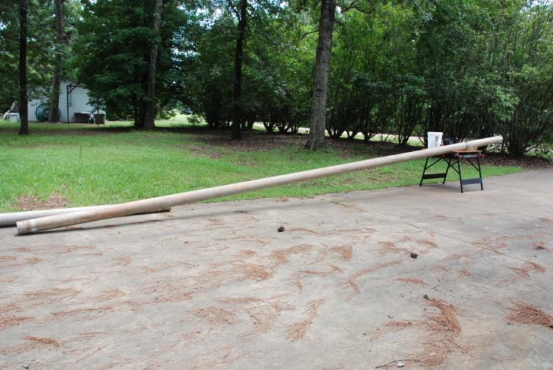
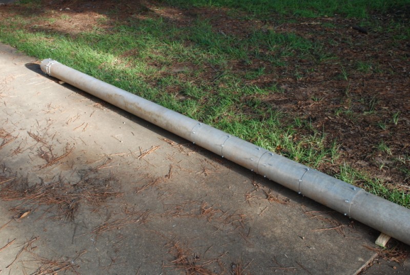
This is the 30 foot section of aluminum pipe that will become the top of the mast.
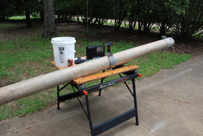
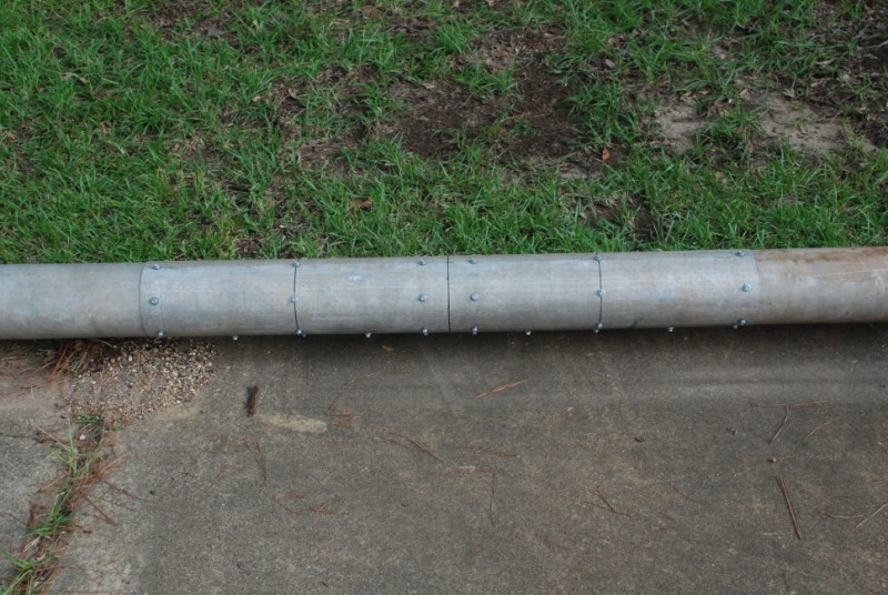
In this photo, I have already completed the top end of the antenna mast. Visible on the mast above the work table is one of the steel clamp bands that were used to lock the sections of pipe together when they were used for irrigation. I reused the clamp bands to firmly tighten the reinforcement bands around the mast pipe before I screwed the reinforcement bands to the main pipe.
Here you can see the reinforcing bands that I placed at several points on the mast pipe. I placed a reinforcing band at every guy line anchor point location, and at the two places where the pipe sections were spliced together. I made the reinforcing sections by cutting lengths of pipe out of a spare pipe. I then slit the pipe sections lengthways from end to end. They naturally "pop" open, allowing me to slide the reinforcing section over the main pipe. The reinforcement bands were then clamped tightly against the main pipe, and the reinforcing bands were permanently attached to the main pipe using heavy galvanized sheet metal screws.
Later, I covered the open end of the pipe with a metal cap to prevent an "Organ Pipe" effect which would cause the entire mast to howl when the wind blows.
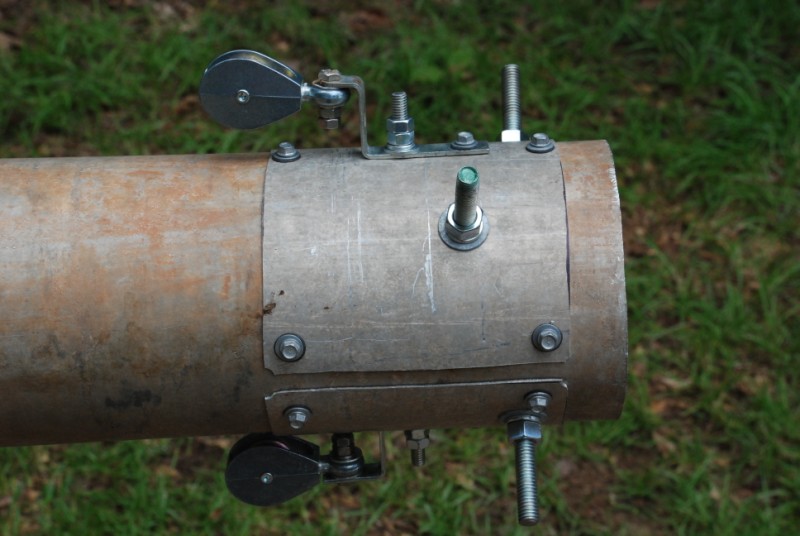
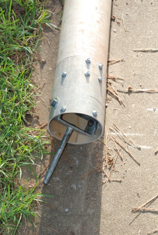
Notice the large threaded rods which pass through the pipe. There are two pieces of this rod at right angles. The guy lines will attach to these rods. Also visible are two pulleys which will be used to hold haul lines so that I can pull things such as wire antennas, to the top of the mast.
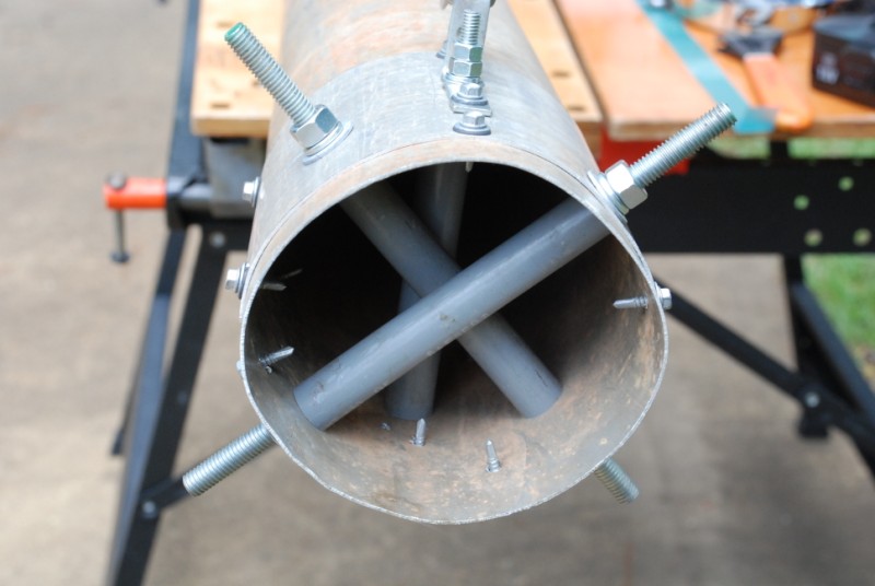
To prevent the aluminum pipe from possibly collapsing due to the load caused by wind acting on the mast, I added some cross pipes inside the aluminum pipe. The threaded rods pass through these pipes. The pipe wall is clamped firmly against the inner pipes by the nuts outside the main pipe. It was necessary to offset the pipes and threaded rods vertically by about an inch so they do not interfere with each other. These pipes were easy to insert in the correct position by hand, but the other two sets of cross pipes at the middle and lower guy line locations were a bit more challenging.
This picture shows the offset between the threaded rods that will hold the top ends of the upper guy lines. It also shows the two pulleys for the haul lines.
The top cap has been installed on the top end of the pipe. This will be the very top of the antenna mast. The cap was made from the bottom of a stainless steel cooking pot from the local thrift store.
This is the attachment location for the middle set of guy lines. It is made the same way as the set at the top of the pipe, by using a reinforcing band around the main pipe, and two inner support pipes through which the threaded rods pass. The nuts of the ends of the threaded rods are just to keep the ends of the threaded rods from becoming damaged when I lay the pipe on the concrete driveway.
Now the fun begins!
Inserting the support pipes inside the main pipe was easy for the top of the mast, but the middle set of guy lines attaches 23 feet further down the mast, which means that the inner support pipes for the threaded rods are a full six feet from the bottom end of the pipe. That means I had to figure a way to stick my arm six feet inside the pipe to get the support pipes in place. The lower guy line position is even worse - at that location, the support pipes have to be inserted 13 feet into the pipe! After they were inserted, then I joined the two 30 foot pipe sections together to form the upper 60 feet of the antenna mast.
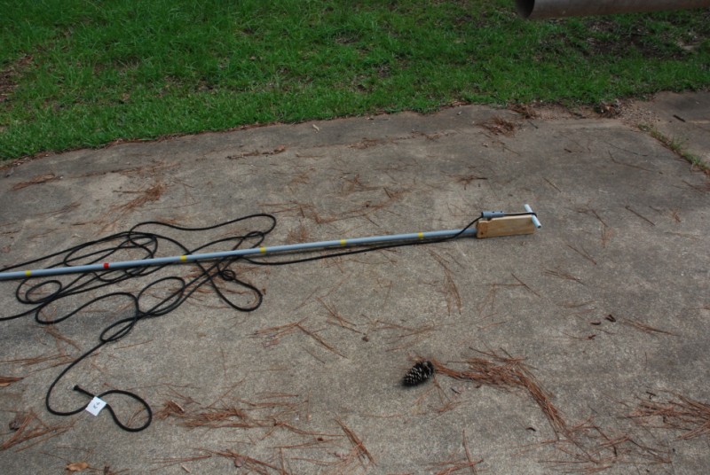
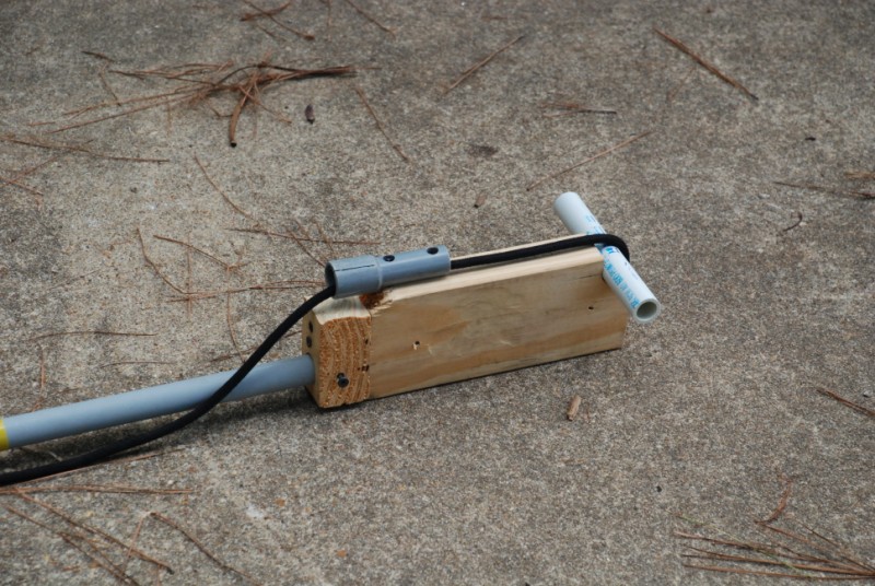
Here's my answer - the W5JGV "Long Arm" that allowed me to insert the support pipes way up inside the main antenna mast pipe. I cut a block of wood that has a notch to hold the support pipe exactly crosswise in the center of the antenna pipe. The support pipe is "grabbed" by pulling on the black rope. That holds the support pipe against the wood block. The handle for the block is a length of PVC pipe.
Side view of the W5JGV "Long Arm."
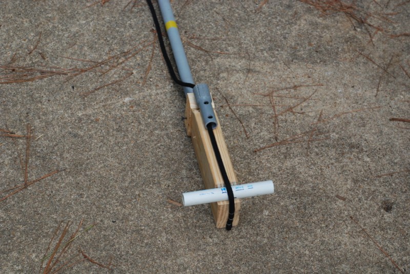
Simple, but effective. You can see how the rope holds the support pipe in place ready for inserting into the main pipe. After the support pipe is in place and the threaded rod has been inserted through the support pipe, the rope is released. Then the "Long Arm" is extracted from the pipe, and the rope pulled back around the support pipe and back out of the main pipe.
It's not too easy to see, but this is one of the two four foot long reinforcing splices I made where the pipe sections join together. That gives me a two foot overlap on either side of the joint. The ends of the pipes at the joint have been rolled over to form an internal lip. This was done at the factory when the pipe was assembled for use as irrigation pipe. I just took advantage of the lip and used it as additional reinforcing when I spliced the pipes together.
Here is the bottom ten foot section of the mast. I have spliced ten feet of additional pipe onto the other two 30 foot sections to make a total antenna mast length of 70 feet. You can see the joint splice at the right side of the picture. On the left side, at the bottom of the antenna a mast, you can see the double thick reinforcement I used at the bottom end of the mast pipe.
At the bottom of the antenna, I had to install a swivel base pin. This is because the guy anchor points are slightly offset by a few degrees from the pivot line of the hinged base which is set in concrete. Since the hinged base cannot be changed, that means that as the mast is raised from the ground to vertical, the top of the mast will have to move about four feet horizontally at right angles to the base hinge. The smaller two inch diameter mast I used for my earlier antenna was able to flex enough so that it did not require the pivot base assemble. However, this mast is so stiff that I was worried that the base insulator might fracture under the stress from the mast as it moved sideways. The hinged pin shown here will drop unto a length of 3/4 inch water pipe that is attached to the base hinge.
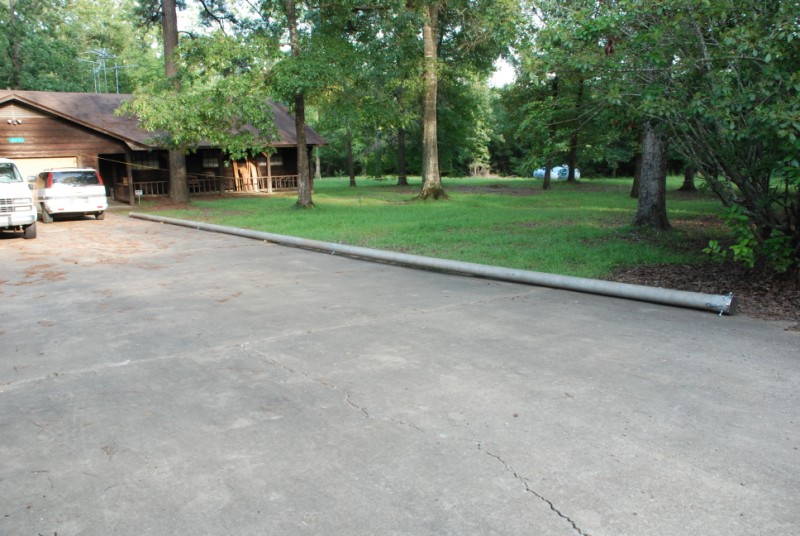
Here is the completed 70 feet antenna mast laying on my driveway, awaiting erection at a later date.
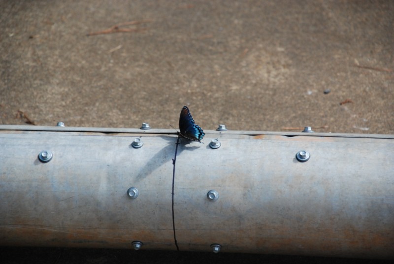
And all the time I was working on the antenna, this little fellow was flitting around me and occasionally stopping to watch me. He stayed with me all day long. I like to think that perhaps Bonnie sent him to watch over me...
More info and pictures as I get the project completed - thanks for stopping by today!
W5JGV
All Pages, photographs, text or other data in any form on this Web Site are Copyright © 2010 and earlier by Ralph M. Hartwell II.