
Antenna Insulators for LF-MF
by W5JGV
July 7, 2002
After WC2XSR / 13 began transmitting at 400 watts, it became spectacularly apparent that the simple PVC pipe insulators would not be up to the task. Late one evening, two of the four insulators supporting the wire antenna for WC2XSR / 13 burned up, allowing the antenna to fall to the roof of my house. This detuned the antenna system so that no further arcing occurred, and thankfully, the roof of the house did not catch fire.
Preliminary investigation indicates that moisture from a late evening rainstorm allowed high voltage RF arc tracking to begin, which resulted in the eventual destruction of the insulators. I suspect that the switch from 10 WPM CW to QRSS3 transmission aggravated the situation, since the full carrier power of 400 watts was applied to the insulators for a much longer period than with the previous 10 WPM CW transmissions. Calculations indicated that there was close to 35,000 volts present on the antenna during high power operation.
Back to the drawing board!
After a suggestion from Jim, M0BMU that the use of Corona Rings might be the answer, I did the proverbial slap-to-the-forehead and went "Duhhh!" as I suddenly remembered my days of Tesla coiling. The toroid on top of the Tesla Coil serves to prevent arcs until the voltage builds up to a high level.
It was suddenly apparent what was wrong with my first insulators. The antenna wire had simply been passed through a hole in the end of the insulator. This resulted in a sharp bend of the antenna wire, creating a very small radius point which was driven by high RF voltage.
The diameter of #14 wire is about 1.6 mm. This small radius resulted in a very high electric field gradient which allows corona discharge to begin at a lower voltage than in the case where the radius is larger. In fact, the local power company uses just such rings in rather large form to prevent arcing and corona from the terminals of some of their high voltage equipment. It seemed reasonable to use something similar for my antenna.
Oops! The remains of the lower wire insulator on the antenna of WC2XSR / 13. This is what happens when too much RF voltage meets a little water and some plastic.
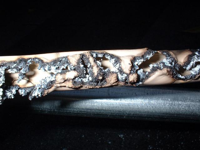
More remains of one of the insulators. Note the interesting meander pattern that the RF made as it tracked down the side of the PVC pipe insulator.
As the corona occurs, it heats the plastic and burns it, making it conductive. This lets the corona discharge track further and further along the insulator, until finally it forms a burnt conductive path across the insulator and destroys it.

Uh-oh! More corona tracking is evident at the output connection of the upper LF loading coil. The damage is not serious yet, but unless this arcing is stopped, the arc tracking will eventually destroy the insulator.
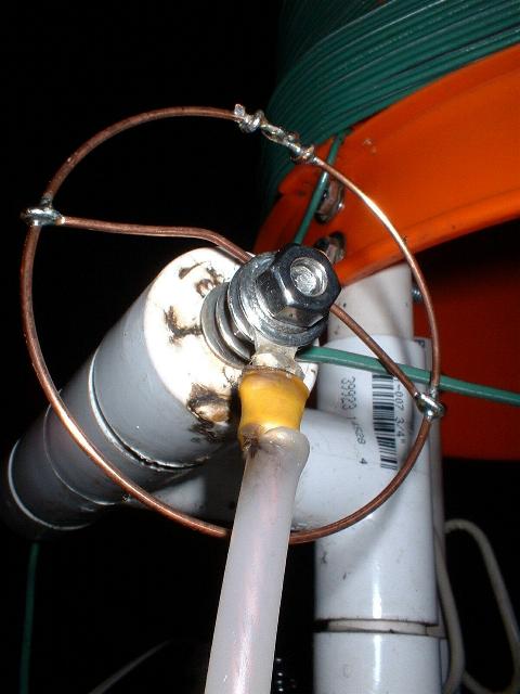
Here you see that I have added a simple and easy to make corona ring made from some #14 copper wire. ( Love that stuff! ) Note that the support wires for the ring are bent back slightly so that the ring is actually placed over the damaged area on the insulator. This establishes an equipotential field between the ring and the plastic insulator, effectively preventing any corona from happening. I'll remove the damaged plastic and smooth the area to prevent further damage.
Since this corona ring is not exposed to wind or other damaging forces, it may be constructed very simply and from light-weight materials, as was done here.

OK, now on to the Big Stuff! I needed to make some sturdy corona rings for the ends of the four insulators which hold up the antenna. The rings are fabricated from a strip of sheet copper and a ring made from soft copper tubing.
The strip, made from 1/32 inch thick stock, is about 1 inch wide by 6-1/2 inches long. A 1/4 inch hole is drilled in the center to pass the mounting bolt.
As shown in the picture above, the copper strip has both ends slit into strips about 1/4 inch wide and about 1 inch long. These make it much easier to bend the end of the strip around the copper ring prior to soldering them together.
The strip must be long enough to allow the finished ring to be offset back about 1-1/2 inches over the plastic pipe cap attached to the insulator pipe. This offset is necessary to establish a potential gradient shield around the end of the wire and the bolt holding the wire to the insulator.

The rings are made by carefully winding a length of 10 mm diameter soft copper tubing around a metal pipe. The pipe should be about 80-90 mm in diameter, which will result in a finished ring diameter of about 100 mm.
After winding the copper tube around the pipe, use a fine tooth saw to cut through one side of the copper tube spiral you have wound. The rings will separate easily after sawing. Smooth the cut ends, and carefully bend the rings so that the cut ends of the tube match up.
Do not solder the ring together yet.
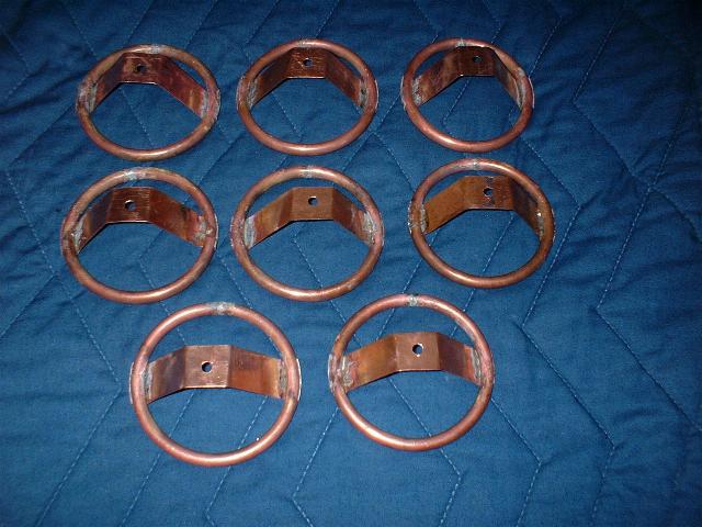
Here is the completed set of eight corona rings after soldering them together. Note that the straps are bent up in a truncated "V" shape to clear the plastic pipe cap and overlap the insulator.
Construction Tips:

This is an example of a good joint. Note that the strap tabs are flat against the ring, with no sharp edges which might start a corona discharge. There is adequate solder to make the joint, but no excess solder is visible.

This is a view of the opposite side of the strap-ring joint when properly soldered.

An assembled Corona Ring insulator fitting. A stainless steel eye bolt passes through the Corona Ring and the end of the PVC cap. A stainless steel fender washer is used on the outside of the pipe cap to prevent the copper strap from being bent backwards in a windstorm.
The loose nut and washers are used to connect the end of the antenna wire to the Corona Ring. The antenna wire must be connected to the Corona Ring, or the RF will arc through the insulation on the antenna wire and cause considerable radio frequency interference.

A view of the inside of the PVC pipe cap which will be cemented to the PVC pipe making up the body of the insulator. A stainless steel fender washer is also used here to prevent the bolt from pulling through the PVC cap when the antenna is under tension.
Note that a thick coating of Silicone RTV compound is used between both sides of the PVC cap and the stainless fender washers to prevent water from getting into the insulators.
Some builders may wish to fill the inside of the PVC pipe with expanding insulating foam. If you do this, be sure that the foam you choose does not release water during curing. Also, make sure that the foam does not allow water to wick through it. Other options are to partially fill the inside of the PVC cap with epoxy adhesive, or plug the ends of the PVC pipe with a slug of Silicone RTV compound.

Here they are, ready to be cemented to the PVC pipe bodies of the insulators.

The first completed insulator. The PVC pipe is 3/4 inch in diameter, and the length is about 12 inches between the rings.
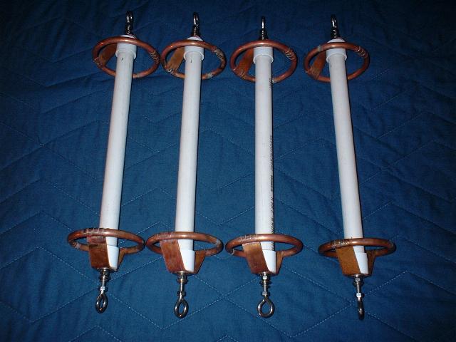
The finished set of four insulators ready for installation on the WC2XSR / 13 transmitting antenna.

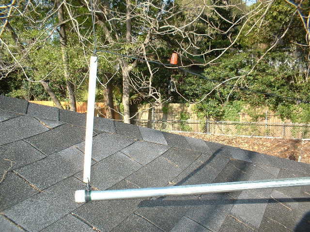
This is the lower wire insulator as installed at WC2XSR / 13. Note that the antenna wire is directly connected to the top corona ring with the stainless steel hardware to prevent arcing through the antenna wire insulation. This is where the first of the plain PVC pipe insulators failed.

This insulator has the highest voltage, since it is at the far end of the antenna. This is where the second of the plain PVC pipe insulators failed.
73, Ralph W5JGV
[Home]
The entire contents of this web site are Copyright © 2002 by Ralph M. Hartwell II, all rights reserved.