
Modifications to the LF Antenna Feed
by W5JGV
July 28, 2002
After the failure of the "T" Standoff Insulator on the upper loading coil followed by the failure of one of the wire standoff pipes, I decided to replace all of the feed wire and insulators between the tuner and the bottom of the vertical antenna wire.
I thought I'd snap a picture of the system before I started the modifications.
Wait! What's that?!?! ANOTHER burned up insulator!!
Take a close look at the white PVC pipe extending from the right side of the tower. Note that it is burned and charred over about half its length.

Ashes to ashes - or, in this case, PVC to ashes. It looks like another case of RF corona discharge causing the plastic to char and become conductive. The damage progresses until the insulator either burns up entirely or the arc tracking shorts out the antenna system.

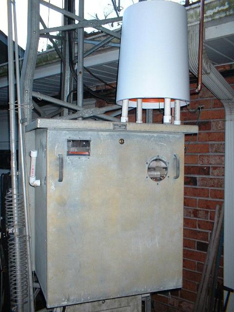
Since it turns out that rainwater collecting on the external upper loading coil causes detuning of the antenna system, I decided to put a rain cover over the coil.
After some searching, I located a plastic trash container which I was able to cut down a bit. It fit very nicely over the Home Depot paint bucket - just as though it had been made for the purpose.
As it was sold, the trash container has a concave bottom, so that it will sit flat on the floor when it is filled with junk. Since that will collect rainwater when it is in place on the loading coil, I had to soften the bottom of the container with a gas flame so that I could dish the bottom outward so that rain would run off when the container was in place over the loading coil.

Here's the covered loading coil as installed on the antenna tuner. The variometer is located inside the cabinet. Note that the "T" insulator which burned up earlier has been replaced by a single PVC support pipe and the coil connections are hanging in the air.

This is partial overall view of the new feed system. We'll look at the various parts of it in the following pictures.
The feed pipe goes up the side of the tower and turns left to meet the bottom of the antenna wire. There is one support pipe holding the feed pipe off the side of the tower, and another standoff insulator holding the far end of the feed pipe by the antenna wire. There are corona rings installed on both insulators
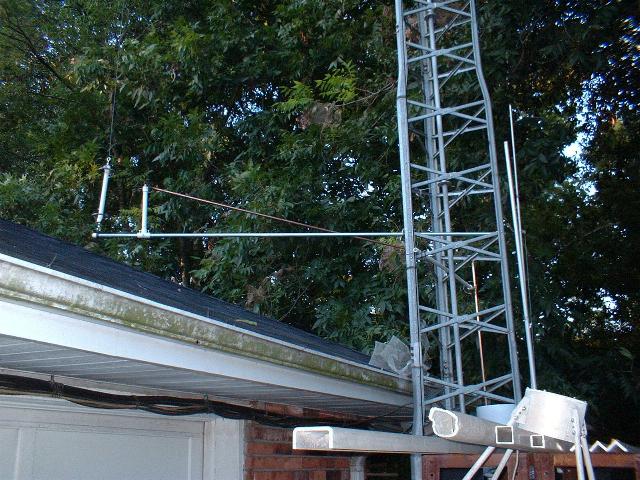
This side view shown the feed pipe going to the standoff insulator by the antenna wire. Note the PVC pipe clamping assembly holding the standoff insulator to the EMT pipe which supports the antenna wire and its bottom insulator.
A front view of the antenna tuner showing the new feed pipe.

The feed pipe is made from 1/2 " copper pipe. The 90 degree elbow fittings are soldered to the pipe. The lower end of the pipe is flattened and drilled so that it may be bolted to the tuners RF output connection at the static gap. The pipe then goes up and to the left so as to clear the rain gutter on the house. The pipe then goes straight up to the support pipe extending from the tower.

Here you can see the details of the connection to the RF output terminal on the antenna tuner. There is about 2 inches clearance between the feed pipe and the edge of the tuner cabinet. There is almost no chance of arcing between the pipe and the wire which is strapped to the pipe, since the wire and the pipe are at the same electrical potential. This wire makes a loop through the antenna tuner cabinet to connect to the RF antenna current ammeter.

The feed pipe then turns and goes straight up to the white PVC support pipe extending from the tower. The feed pipe is fastened to the PVC pipe by a supporting tab which is soldered to the feed pipe. The feed pipe then turns right and goes to the antenna wire.

Standing on the roof and looking down at the top of the tuner. The feed pipe is visible coming up from the tuner to the support pipe (not visible in this picture). The white cover is the rain cover for the upper antenna loading coil.

Standing a couple of rungs higher on the tower, you can see the PVC support pipe on the tower which holds the feed pipe. Although it's a bit hard to see, the pipe extending across the roof is actually parallel to the ground. It connects to the lower end of the antenna wire. The corona ring and support connection for the feed pipe are faintly visible.

A view of the feed pipe where it connects to the support pipe from the tower. Note the corona ring. This is a Quick & Dirty version of the ones I built for the antenna insulators. Time will tell if these simpler versions will work adequately.

A view from the other side of the support pipe. You can see the soldered-on support tab for the feed pipe. Note that the corona ring is BEHIND the feed pipe support tab. This is needed to properly shape the electrostatic field to prevent arcing from the bolt in the end of the PVC pipe cap.

This view shows the copper support tab which is soldered to the feed pipe. You can also see the way in which I have formed the support wires for the corona ring. All stainless steel hardware is used for the connections.

An overall view of the rooftop portion of the new feed system.
To the left is the antenna insulator hanging from the bottom of the antenna wire. To the right of the antenna insulator is the clamped-on PVC support insulator which holds the end of the new feed pipe. There is a corona ring on the top of the support insulator. A coiled spiral made of #14 copper wire connects the end of the feed rod to the bottom of the antenna wire. This allows for antenna wire movement in the wind.

A close-up view of the antenna insulator and feed pipe insulator.

Four 1/4 " bolts are screwed through the PVC pipe "T" and compress the wall of the EMT tube to prevent the feed pipe standoff insulator from slipping out of position.

Here you see the corona ring on the top of the feed pipe standoff insulator. Again, note that the corona ring is mounted BELOW the feed pipe so as to shape the electrostatic field properly.

A close-up of the corona ring and connections.

A radio wave's view looking up the antenna through the corona ring of the bottom insulator.
The antenna wire is easily visible all the way up to the antenna top insulator. The curved shadow at the top of the picture is the corona ring.
73, Ralph W5JGV
[Home]
The entire contents of this web site are Copyright © 2002 by Ralph M. Hartwell II, all rights reserved.