
A Motor Drive for your Variometer
by W5JGV
No more trudging out to the antenna tuner in the rain!
Everyone who has set up a low frequency base loaded antenna is aware of the very narrow bandwidth of the antenna system, and the seemingly constant need to retune the antenna whenever anything in the surrounding area changes the antenna tuning.
One of the easiest ways to adjust the antenna tuning is to use a variometer or a variable capacitor. Using either approach requires that someone go out to the antenna tuning unit and manually adjust the variometer or variable capacitor. After losing track of how many miles I seem to have trudged between the house and the tuner, I finally decided to do something about it.
I used a surplus DC gearmotor, some fishing leader, some PVC pipe fittings, a potentiometer and a bit of garage engineering to produce this simple, but effective, drive unit. At present, I control it with a pair of push-buttons and a 15 volt power supply. This lets me run the motor - and the variometer - clockwise or counter-clockwise as needed.
While adjusting the variometer, I monitor the antenna current with my home-brew remote RF ammeter (that's a topic for another article.) I just press the buttons and "Tune for Max!" The feedback potentiometer provides a metering voltage proportional to the position of the variometer. I read this on a simple DC voltmeter calibrated in percent of rotation from 0 to 180 degrees.
Hidden under the red plastic bucket is the motor drive and feedback potentiometer that operates the WC2XSR/13 antenna tuner variometer.

The motor drive assembly is seen atop the antenna tuning unit (ATU) cabinet.
The variometer shaft is attached to the large white wheel seen in the middle of the side of the ATU cabinet. The clear plastic pointer carries a strong magnet in the white box which is glued to the end of the pointer. This magnet operates a reed limit switch when the pointer reaches either limit to its travel. The limit switches are inside the two white boxes to the left and right side of the variometer shaft. The aluminum tape on the cabinet holds the limit switch wires in place and protects them from the weather.

A close up view of one of the two limit switches on the ATU cabinet.
These switches are ordinary normally-closed alarm system switches, purchased at Radio Shack. They interrupt the drive signal to the motor when the variometer has reached its rotation limit.

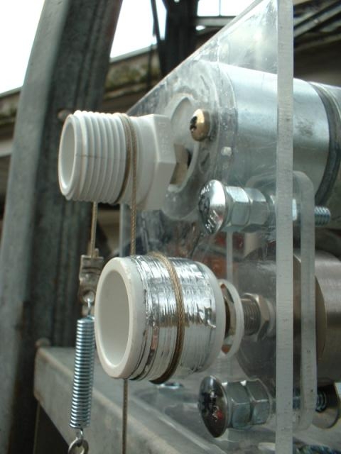
A closer view of the variometer drive.

The variometer drive shaft is a length of 1/2" ID black PVC pipe that is commonly used for lawn irrigation. The shaft extends through the variometer coil, and is screwed into a PVC pipe coupling adapter. In order to get the ratio between the motor drive wheel and the variometer shaft correct, it was necessary to glue another PVC pipe adapter over the outside of the PVC pipe adapter on the variometer drive shaft. You can see the two individual PVC adapters if you look at the right side of the assembly. You can also see a slightly darker but transparent circular plastic window which is glued over the center of the assembly. This is just to prevent insects and rain from entering the ATU cabinet through the hollow variometer shaft. A twice-around wrap of the drive line is all that's required to control the variometer shaft.

Here's the motor drive assembly on top of the cabinet.
You can see the wires connecting the drive motor (the large cylinder) and the feedback potentiometer (the small stubby cylinder below the motor.) These wires go back to the control panel inside the house. Because the motor operates on 12 to 24 volts and only a few hundred milliamperes, I was able to use a length of CAT-5 cable to connect the motor to the control panel
The motor is a surplus DC gearmotor that rotates only a few RPM when connected to 12 volts.
Reversing the polarity of the voltage also reverses the direction of rotation. The drive belt is a length of plastic coated twisted stainless steel fishing leader wrapped around the drive wheels. Friction keeps the wheels aligned with each other. The silver colored spring seen in the background maintains the correct tension on the drive line so the line does not slip. The motor and feedback potentiometer are mounted on pieces of 1/4" thick clear plastic. There's no particular reason for using plastic; I just happened to have a lot of it handy. A metal plate would do just as well.

In this view you can see that while the motor is firmly affixed to the bracket, the feedback potentiometer is mounted on its own separate plastic plate.
This was to allow me to adjust the position of the pulley in relation to the motor drive pulley. Also note that the lower bolt has a large washer which is used to clamp the body of the potentiometer in place. This allows me to rotate the body of the potentiometer so as to calibrate the potentiometer end stops with relation to the variometer. The potentiometer is a continuous rotation unit; this makes adjustment much easier.

Looking at the feedback potentiometer drive wheel from the other side.
Notice the multiple layers of aluminum foil that are wrapped over the drive wheel. This is to slightly change the diameter of the wheel to make sure that the potentiometer drive wheel completes the required 340 degrees of rotation when the variometer shaft drive wheel has rotated 180 degrees.
73, Ralph W5JGV
[Home]
The entire contents of this web site are Copyright © 2002 - 2004 by Ralph M. Hartwell II, all rights reserved.