
Interfacing the Ameritron ALS-1300 to the FlexRadio-5000A Using the ARI-500 Interface
by W5JGV
First Posted - 11 February 2011
Revised V1.01, 12 February 2011 - Corrected typos
Revised V1.02, 04 June 2011 - Corrected RJ-45 wire color code
A Cookbook procedure to get your ALS-1300 talking to your FlexRadio-5000A
OK, so you bit the bullet and now you have some nice, new and expensive Ham gear on your operating desk. You've read the manuals, and searched the Internet, but you still can't quite figure out how to make your new Ameritron ALS-1300 amplifier working with your FlexRadio-5000A. You know it should band-follow and all that, but you're wondering just how do I make it do that?
This article should help you through the steps of making all that new hardware and software "play nice" together. The result will be a new experience in Amateur Radio operating. This article will set out the basics of making your ALS-1300 band follow your FlexRadio-5000A by using the ARI-500 interface adapter, and automatically change the drive level from the FlexRadio-5000A to the ALS-1300 amplifier as required on the various Amateur bands.
To begin, you must have the F5K (Flexradio 5000A) and its companion PSDR (PowerSDR) operating program working correctly. For the purposes of this article, I will assume that you are using version 1.18.6 of PowerSDR.
You will need to have a parallel port interface in the computer that is running PSDR. This port is required to transfer the BCD band data between the F5K and the ARI-500. If your computer does not have a hardware parallel port interface installed, you will need to add one to the computer.
You will need to make up a data cable to connect the ARI-500 to the F5K. The cable will have a male DB25 connector on one end, and an RJ45 connector on the other end. The ARI-500 is shipped with a 12-foot long cable, which has an RJ45 connector on one end of the cable. The other end of the cable has nothing on it, so you will need to install a male DB25 connector on that end of the cable. It's easy, and the details on how to do this are presented a little further down the page.
To get the PSDR software to talk to the ARI-500, you will need two additional pieces of software. The first is DDUtil, which transfers data between PSDR and the ARI-500. The program is available at:
http://k5fr.com/binary/DDUtil18701_Setup.zip
Full documentation for DDUtil is available at:
http://k5fr.com/ddutilwiki/index.php?title=Main_Page
The second is VSP Manager, which allows you to create the virtual serial ports that are required to allow PSDR to transfer data between various other programs, including DDUtil.
The program is available at:
http://k5fr.com/binary/DDUtil18701_Setup.zip
Documentation for VSP MANAGER is included in the program.
After downloading the programs, install them on your PSDR computer.
The next order of business is to make up the data cable. The interface between the F5K radio and the ALS-1300 amplifier is made through the ARI-500. To connect the ARI-500 to the ALS-1300, you will use the two supplied RJ45 to RJ45 computer network patch cables that are supplied with the ARI-500. To connect the ARI-500 and the F5K, you need to connect a data cable between the ARI-500 and the computer that runs the PSDR software that controls the F5K. When everything is working, the DDUtil program will output the band data on the parallel printer port (LPTn) in the computer. Because the standard LPT port is a female 25 pin DB25 connector, the data cable needs to be an RJ45 connector on one end, and a DB25 male connector on the other. Unfortunately for F5K owners, such a cable is not readily available. You will have to "roll your own." Here's how to do it.
Start by taking the end of the factory supplied cable that has the RJ45 attached. Hold the RJ45 connector so that the gold pins on the RJ45 connector are facing up. The cable coming from the rear of the connector should be pointing back at you.
If your cable has been wired correctly, the colors of the wires should correspond to the connector pins as follows:
Pin 1 - White with Orange stripe
Pin 2 - Orange
Pin 3 - White with Green stripe
Pin 4 - Blue
Pin 5 - White with Blue stripe
Pin 6 - Green
Pin 7 - White with Brown stripe
Pin 8 - Brown
If these colors do not match your cable, please make a new chart of the wire colors vs. pin numbers.
Now you need to make the following connections between the unterminated end of the cable and the male DB25 connector:
DB25 pin 2- to - RJ45 pin 7 - BCD Band Data A
DB25 pin 3- to - RJ45 pin 6 - BCD Band Data B
DB25 pin 4- to - RJ45 pin 5 - BCD Band Data C
DB25 pin 5- to - RJ45 pin 4 - BCD Band Data D
DB25 any pin 18 to 25 - to - RJ45 pin 1 - ground
As you can see, you only have to connect a total of five wires in the cable to the DB25 connector. Note that this cable only transfers the band data between the F5K and the ALS-1300. It does NOT carry the PTT signal. In order to key the amplifier from the F5K, you will have to make a connection between one of the Amp Relay TX connectors on the rear of the F5K and the Relay input on the rear of the ALS-1300. More on this later.
As it comes from the factory, the ARI-500 keys the ALS-1300 through one of the RJ45 cables, but only if the control cable from the radio to the ARI-500 carries the TX/RX control signal. This signal is not present from the parallel port on the computer, and the Flex-5000A does not supply it except as a hardware switch closure available through the rear panel jacks on the transceiver.
Also, the first ARI-500's shipped had no provision to place the ALS-1300 in standby without shutting down power to the ALS-1300. Later ARI-500's had a small unmarked switch added to the front panel of the unit. This switch breaks the internal keying line going to the RJ45 connector. This allows you to place the ALS-1300 in standby for low power operation or operating an external automatic antenna tuner.
If you have an external auto tuner, you must bypass the ALS-1300 to allow low power to be sent to the tuner so it won't be damaged during the tuning cycle. You also need to let the ALS-1300 be placed in bypass mode by the antenna tuner in case the tuner senses a high VSWR and "wants" to retune.
The problem with the ARI-500 as supplied is that there is no way to loop the amplifier keying line through the tuner, since the keying line is within the RJ45 cable. Although you could cut into the RJ45 cable, a more elegant way is to modify the ARI-500. By modifying the ARI-500, the cables will stay "standard," so replacing them in the event of loss or damage will not require modifying the new cables.
What you do is unsolder and lift one end of a surface mount diode off of the ARI-500 circuit board, install a pair of RCA jacks on the rear panel, and solder two wires from the RCA jacks to the pads where the diode was connected. The diode package has three leads, because it is a dual diode package. The other two leads of the diode package will remain soldered to the printed circuit board. Those changes allow you connect the amplifier key line coming from the ARI-500 through an external RCA to RCA cable to the amplifier key line input jack of the auto tuner and then from the tuner amplifier key line output jack to the key line input jack of the ALS-1300 amplifier. The factory installed enable/disable switch on the ARI-500 will then also work to place the amplifier in standby mode when desired.
If desired, the ARI-500 may be returned to unmodified functionality by connecting a jumper cable between the two new RCA jacks on the rear panel.
The following pictures will show you how I performed the modification.
The ARI-500 as shipped from the factory.
I added the switch label - it was unmarked as delivered. The mounting tape on the top of the unit was added to hold it in place under a shelf.

Rear view of the ARI-500 after adding the two new RCA jacks.
Normally only the left jack - Amp Key IN - will be be used to connect to the ALS-1300.

Overall view inside the ARI-500.
The factory-added switch with it's associated red wires and ferrite filter beads may be seen here.
The two new RCA jacks and their associated black wires are connected to the surface mounted diode D1, which is seen near the right side of the picture.

The wires from the new RCA jacks are routed to diode D1 this way.
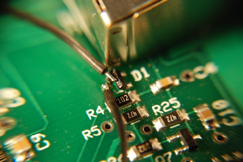
Using thin solder wick and a small soldering iron tip, carefully remove most of the solder from the center lead of the diode.
Then, while melting the remaining solder on the center lead of the diode, use a pointed solder pick to carefully lift the diode center lead free of the circuit board pad.
Carefully bend the body of the diode up to about 45 degrees, being careful not to break either of the other two diode leads which are still soldered to the circuit board.
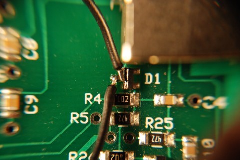
Connect the two wires from the RCA jacks to the circuit board pad and the center lead of the diode.
The IN jack connects to the center lead of the diode, and the OUT jack connects to the circuit board solder pad where the diode center lead used to go.
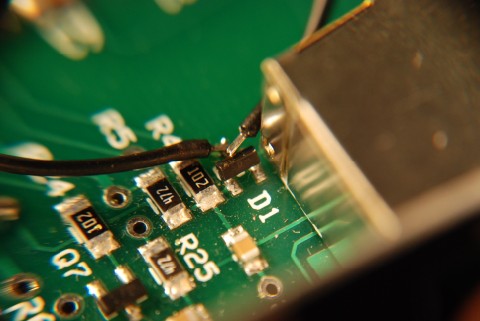
Another view of the completed modification.
After the cable is assembled and tested (you did check it with an Ohmmeter for continuity and pin-to-pin shorts, didn't you?) and complete, you will need to make the following hardware connections between the F5K, the ARI-500, and the ALS-1300.
1) Connect the two factory supplied RJ45 cables between the ARI-500 and the ALS-1300 as follows:
ARI-500 AMP A jack to ALS-1300 REMOTE A jack, and,
ARI-500 AMP B jack to ALS-1300 REMOTE B jack.
2) Connect the RJ45 to DB25 data cable you just finished wiring between the ARI-500 RADIO jack and the computer's parallel DB25 port.
There will be no connections required to the ARI-500 REMOTE A & B jacks unless you are using the ALS-500RC. For the purposes of this article, I will assume that you will not be using the ALS-500RC.
3) If you are using an unmodified ARI-500, you will need to connect one of the F5K's Amp Relay TX connectors (1, 2, or 3, your choice) to the ALS-1300 RLY jack. This allows the F5K to key up the ALS-1300 when the F5K goes into transmit mode.
With an unmodified ARI-500, the front panel switch will be inoperative, and you cannot use it to place the amplifier in standby. It will be on whenever the ALS-1300 main power switch is turned on. This means that in order to take the amplifier off-line for tuning, you will have to turn off the main power switch on the amplifier. Modifying the ARI-500 eliminates this inconvenience.
If you are using an automatic antenna tuner such as an MFJ-998, then you should route the amp keying line through the AMP ENABLE IN and AMP ENABLE OUT jacks on the rear of the MFJ-998. This connection allows the tuner to unkey the ALS-1300 amplifier when low power is required to retune the antenna system. Be aware that the safety shutdown in the ALS-1300 is very fast, and in many cases the amplifier may shut itself down with a SWR or PA fault when the antenna tuner goes to work. There is nothing wrong; it's just that the ALS-1300 reacts instantly to protect itself, faster than the tuner can tell the ALS-1300 to power down.
OK, now it's time to start tweaking all the bits and pieces of the software that make this thing so much fun.
If you have modified your ARI-500, connect the RCA cables for the amplifier keying line according to the diagram below. The two RJ45 cables are supplied with the ARI-500. Note that the use of the auto tuner is optional.

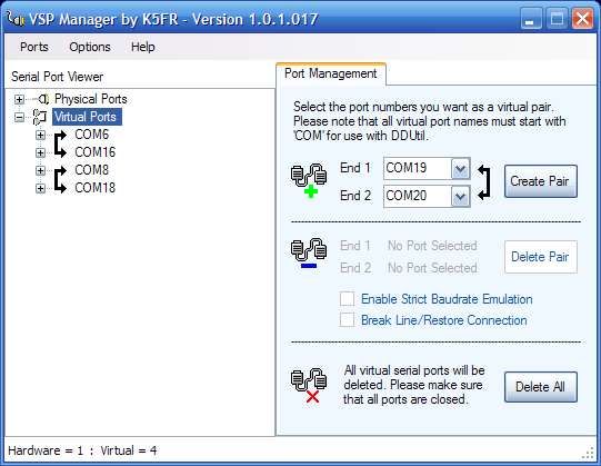
Open the VSP Manager program. The program has only one screen. Its sole function is to allow you to create virtual serial ports inside the computer so that various programs can interchange data. What you will do it to create two pairs of Virtual Serial Ports using the controls in the right hand pane.
1) Using the pull down box for END 1, select Port 6
2) Using the pull down box for END 2, select Port 16
3) Press the CREATE PAIR button.
4) Using the pull down box for END 1, select Port 8
5) Using the pull down box for END 2, select Port 18
6) Press the CREATE PAIR button.
7) In the left hand pane, press the [+] button to expand the Virtual Ports. There should be two port pairs visible, COM6, linked to COM16, and COM8, linked to COM18.
When you are done, the screen should look like this:
8) Close the program.
1) Open the SETUP tab in the PSDR program.
2) Open the CAT Control tab.
3) In the CAT Control pane, set the following:
PORT = COM6
BAUD = 1200
PARITY = NONE
DATA = 8
STOP = 1
4) Check the ENABLE CAT box
5) In the PTT Control pane, set the following:
PORT = COM18
6) Check the RTS box
7) Check the DTR box
8) Check the ENABLE PTT box
9) In the "ID as" pull down box, select PowerSDR
The remaining check boxes should be unchecked.
When you are done, the screen should look like this:

10) Close the PSDR SETUP box.
You must enter the correct parallel port data when you are setting up the DDUtil program. Most computers will have the port named as LPT1, LPT2 or LPT3. If you have installed an add-in card for the parallel port, then the port name may be something different, such as LPT5. You will need to determine what the correct port name is.
1) Right-click on MY COMPUTER.
2) Select PROPERTIES.
3) Select the HARDWARE tab.
4) Select DEVICE MANAGER.
The Device Manager screen opens.
5) Scroll down to the PORTS (COM & LPT) listing and then click the [+] button to expand the selection.
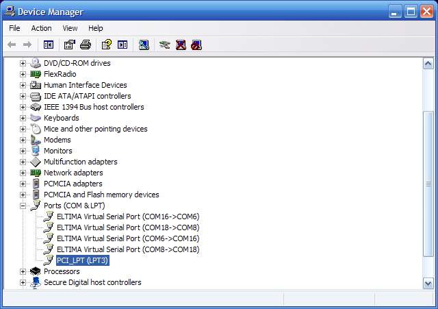
6) Right-click on the LPT listing and select PROPERTIES.

7) Note the line that reads I/O RANGE. Note the FIRST number. In this case, it is FDF0 in Hexadecimal notation. Whatever yours is, write it down.
8) Open the Windows Calculator.
9) In Calculator, select the VIEW menu, and select SCIENTIFIC.
10) Select the HEX button.
11) Enter the Hexadecimal number you previously wrote down into Calculator. The screen should look like this:

Of course, the Hex value will be whatever your number was.
12) In Calculator, select the DEC button.
13) Note that the number Hex number you previously entered has been converted to a Decimal number, as in this screen:
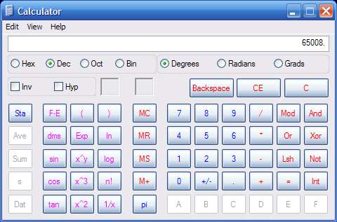
14) Write this number down, it is what you will need to enter in DDUtil for the Parallel Port number.
Here we will make the connection between the F5K's PSDR software and the ARI-500.
1) Open the DDUtil program and select the PORTS tab.
2) In the SERIAL PORTS area, using the Radio CAT pull down box, set the port to COM16.
3) In the PARALLEL PORT area, in the Port Selector pane, select OTHER.
4) In the PORT NUMBER box, enter the decimal number you obtained in Calculator.
Note that even if your computer uses LPT1, 2, or 3, checking the LPT1, LPT2, or LPT3 buttons does not seem to work correctly all the time. Doing the numeric conversion and entering the number as an OTHER port seems to work better. (At least it does for me.)
5) In the DATA SIGNALS pane, check the ENABLE box.
The screen should look like this:

Because the F5K can provide 100 watts of RF output, which is more than enough to drive the ALS-1300, you must determine the actual drive level required for your particular ALS-1300 to avoid distortion and possible damage to your amplifier.
My ALS-1300 can be driven to full linear output with less than 60 watts on most bands. Because the correct drive level for linear operation varies slightly with frequency, it is necessary to run a drive level test on all bands in order to determine what the correct levels will be.
The procedure is as follows:
1) Connect the ALS-1300 to a dummy load capable of absorbing the full amplifier output for 5 minutes or more. Do not power the amplifier on. Without mains power, the amplifier will be in bypass mode, and will connect the Flex-5000A directly to the dummy load.
2) Connect the RF output of the Flex-5000A to the input of the ALS-1300.
3) Connect an oscilloscope across the dummy load so you can observe the RF envelope waveform.
4) On the PSDR main screen, set the BAND to 160 Meters.
5) On the PSDR main screen, go to the MODE panel and set the mode to DIGL.
7) From the PSDR Main Menu bar, select SETUP.
8) In the SETUP window, select the TESTS tab.
9) In the TWO-TONE TEST panel:
Set Freq #1 to 700
Set Freq #2 to 1400
Set POWER to 10

10) In the Two Tone Test panel, press the TEST button to key the Flex-5000A.
11) Observe the RF waveform envelope on the oscilloscope screen, and make sure that the Flex-5000A is producing an undistorted two-tone waveform.
12) Press the TEST button again to unkey the Flex-5000A.
13) Increase the POWER level by 10 units.
14) Repeat steps 10 through 14 until you have reached 100 watts in the power setting. At each increment, the RF output of the Flex-5000A should increase, and the two-tone RF envelope should remain clean and undistorted at all power levels.
15) Unkey the Flex-5000A.
16) Reduce the POWER level to 10.
17) Power on the ALS-1300 amplifier.
18) In the Two Tone Test panel, press the TEST button to key the Flex-5000A. The ALS-1300 should also key-up and produce RF power.
19) Observe the RF waveform envelope on the oscilloscope screen. You will be looking at the RF output from the ALS-1300 amplifier. Observe the oscilloscope screen and be sure that the ALS-1300 is producing an undistorted two-tone waveform.
20) Press the TEST button again to unkey the Flex-5000A.
21) Increase the POWER level by 5 units.
22) Repeat steps 10 through 14 until you observe on the oscilloscope screen that the two-tone waveform envelope is beginning to "flat-top" or distort.
23) When the point of distortion is reached, unkey the Flex-5000A.
24) Note the numerical value in the POWER box. Subtract 5 from the value shown. The result is the power level that should not be exceeded for your ALS-1300 on that band..
25) On the PSDR main screen, change bands to 80 Meters.
26) Repeat steps 16 through 24 for the remaining frequency bands, at each band, recording the highest drive level shown in the POWER box that produces maximum undistorted power output from the ALS-1300. You will need these levels when you set up DDUtil.
Now you will tell DDUTIL what the correct drive levels are from the F5K to the ALS-1300.
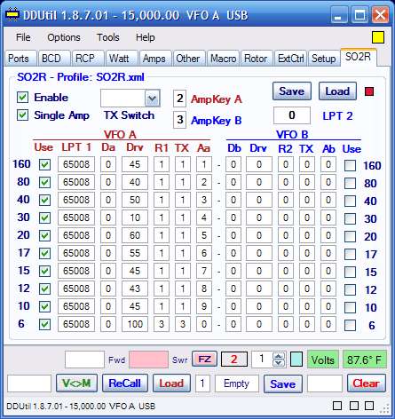
1) Open the SO2R tab.
2) Check the tick boxes labeled ENABLE and SINGLE AMP.
3) In the "AmpKey A" box, enter the F5K Relay Key 1, 2, or 3 that you are using to key the ALS-1300. I used 2, so that is what the screen shot shows.
4) In the "AmpKey B" box, enter any number 1 through three. Unless you are going to use a second amplifier, it does not matter what you enter here, but the program expects a number from 1 to three.
5) In the VFO A area, place a check mark in the "USE" column for each band you want the amplifier to operate. An unchecked box will result in the ALS-1300 remaining bypassed when operation on that band is attempted.
6) In the LPT1 column, enter the decimal value you previously calculated for the parallel port your computer is using for the band data transfer to the ARI-500. In my case, for LPT3, it is 65008, as shown in the screen shot. Do this for each band on which you want the ALS-1300 to operate.
7) Enter zero in the "Da" column for all bands.
8) In the "Drv" column, enter the RF drive level you previously measured for each band.
9) In the "R1" and "TX" columns, enter the numbers of the antenna ports on the F5K for receiver 1 and the transmitter for each band. Note that I have my system set to use antenna 1 for both TX and RX for all bands except for 6 Meters, where I use antenna 3.
The numeric value in the "Aa" column determines which band the ALS-1300 will switch to when the F5K is operating on the selected band. As the program comes "out of the box," the numbers go from 1 on 160 meters through 9 on 10 meters, and 0 on 6 meters. This is correct, and will cause the ALS-1300 to follow the F5K on all bands, except for 6 meters, where the ALS-1300 will be bypassed.
10) Press the "SAVE" button to save the data.
When you are done, the screen should look like this:
11) Now go to the main tool bar of the program and select OPTIONS, then PROFILE SAVE.
12) Name the profile and save it, so that you can easily reload it if something crashes later on.
Note that unchecking the ENABLE tick box causes DDUTIL not to key the amplifier. Also, the power output of the Flex-5000A will revert to whatever was previously set in the DRIVE tab on the PSDR main screen. (It may be necessary to switch bands and then back again to get the PSDR power level to change when the ENABLE box is unticked.)
Now open the BCD tab, and check the ENABLE box. The screen should look like this:
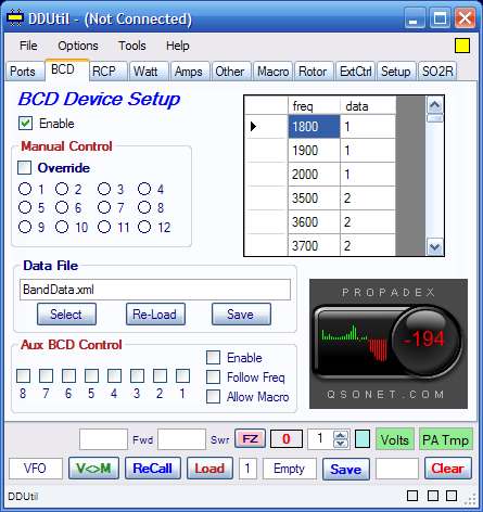
Minimize the DDUtil window; do not close it. Note that the DDUtil program must be running while PSDR is running or no data will be transferred between PSDR and the ARI-500. On my computer, I have DDUTIL set to start up when Windows starts.
Power on the computer.
After the computer is fully booted, power on the Flex-5000A.
Start DDUTIL.
Start PSDR.
Power on the ALS-1300.
Note that the OPERATE/STANDBY switch on the ALS-1300 is not used when the ARI-500 is used. Leave the switch in the STANDBY position.
To reset an amplifier fault, it is necessary to turn the amplifier power switch OFF.
Wait at least 5 seconds for the power supply to completely power down, then return the amplifier power switch to the ON position.
Rapid power switch cycling may damage the amplifier or power supply.
73, Ralph W5JGV
[Home]
The entire contents of this web site are Copyright © 2002 - 2011 by Ralph M. Hartwell II, all rights reserved.