
The AC Power and Emergency Generator System at W5JGV
by W5JGV
First Posted 22 Jul, 2007, updated 9 Nov 2007
What does this have to do with AC power?
Nothing! But it will give you an idea of the kind of place that we are living in now.

Since we're showing off the place a bit, here's a view of what will become the antenna field for W5JGV.
The pile of dead trees you see next to the new foundation work are close to the area where the 500 KHz vertical antenna will be constructed.

The new ham shack / art studio / storage building will be placed where you see the fresh earth. Construction should begin Real Soon Now.
As soon as we moved in, we realized that we would be making much more use of our emergency generator. I think the power failed twice the first day we were here. (I think we've had about one power outage each day since then. Some are brief glitches, some last an hour or more.) I quickly set up our little Onan 5 KW genset on the back porch. The house has an outdoor kitchen on a raised wood deck. I mounted the generator in the kitchen area, and added a two-sided wood and fiberglass weather screen as you see here.

The genset weather screen surrounding the 5 KW Onan genset.

Yep! It's really in the kitchen!

The black case on the table holds the engine starting battery, which is kept charged by a small automatic battery charger. The yellow tube carries propane fuel to the generator engine. There is an electric solenoid valve that cuts off the fuel supply whenever the genset is not running. The genset is on wheels so it can be moved, but here it is mounted up on concrete blocks in this semi-permanent installation.
There is a white plastic carpet screen mounted upright just to the right of the genset cooling fan. Since the unit was designed to exhaust the cooling air downwards, it was necessary to redirect the exhaust cooling air upwards towards the ceiling where it exits the area. Note the exhaust pipe simply ends in a small muffler right above the genset. Since the area is well ventilated, this is adequate, but I don't allow anyone to stay in the area for very long when the genset is running.
The combination of the weather screen and wooden walls on the other three sides of the kitchen area make the running noise surprisingly low from more than a few yards away. In any event, there are no close neighbors around to complain! There is a manual safety disconnect switch to disable the genset when working on then system, and a smoke detector is installed in the overhead. This shuts down the genset and turns off the fuel supply should a fire or smoke situation occur.

This junction box contains the electronic logic and generator fuel lockout relay that stops the generator is the smoke detector is tripped.

A view from the generator looking at the backside of the weather enclosure. It's simple, but sturdy enough to handle most storms. Note the gap between the floor boards. These let cooling air into the area from beneath the raised deck. Hot cooling air and exhaust gasses rise to the top of the area and flow outside over the top of the right side wall of the enclosure. There's lighting and a ceiling fan for operator comfort when working on the genset.
The existing electrical system had a 200 Amp load panel which was connected directly to the utility meter. I had to break into the circuit and install an automatic transfer switch and the necessary components to allow me to operate both my existing 5 KW genset and the new 27 KW genset I have ordered.
However, before I could start upgrading the electrical system, I had to figure out how to keep basic stuff such as the refrigerator and freezer running while I ripped everything apart. Since the old garage I am using as a workshop has its own separate power feed, I decided to borrow some power from the to backfeed the load panel in the house until I completed the electrical system upgrade.
It is about 125 feet from the shop to the house, and I knew I could not get enough power by simply stringing an extension cord between the buildings. Something better was needed. I decided to build my own high voltage transmission line. Looking through the Junque I had lugged here from New Orleans, I located a pair of 5 KW transformers that looked as though they would work. Here's a picture of one of them that I placed at the house end of my temporary High Line.

The two transformers were set up to step up the 240 volts from the service at the workshop to 480 volts, and then back down to 240 volts at the house. Since they were rated at about 5 KW each, I was able to use 12 Gauge Romex between the transformers for the 480 volt section. (Yes, the Romex is rated to 600 volts - I checked!) Some heavier 8 Gauge cable connects to the 50 amp air conditioner breakers in the house load panel to backfeed the panel. In the shop, the other transformer is fed from my welding machine outlet.
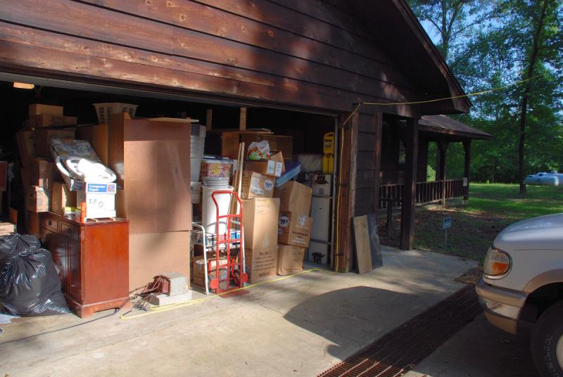
Here you can see the garage is still full of stuff from the move. Most of this will go into the new building that will be the ham shack / art studio / storage building. You can also see the yellow Romex wire leading from the power transformer back to the shop, and the black cable going to the house load panel.

From tree to tree, the high line makes its way from house to shop. (You have to look closely to find the wire.)
Let's see what I had to start with before I began this project...

As you can see, things were pretty simple. There was just the meter panel, and an add-on circuit breaker box for the electric furnace. The load panel for the house is located directly behind the meter panel.
What I needed to do was to install a generator automatic transfer panel and the necessary hardware to make everything work by itself. There's a lot to do...
Low let's look at an overall picture of what's been done to this point.

The 5 KW generator is mounted in the outside kitchen at the left side of this picture. The lower of the two gray conduits feeds running along the wall carry the AC power from the genset to the electrical panels, while the upper conduit contains the low voltage control wires that operate the genset.
Visible in the bottom of the picture is the new slab for the 27 KW genset.
Starting from the utility company's weatherhead, the incoming power drops down to the meter panel. Originally, the power then went straight through the wall into the house where it fed the load panel. The gray electrical box that has the white PVC conduit going up the wall from it and that is mounted just to the left of the meter panel has the 80 amp circuit breakers for the 20 KW electric furnace, which was added to the house several years ago.
Originally, these breakers were fed through a short conduit jumper that ran between the meter panel and the breaker box. I left the conduit in place, but rewired the breaker feed. This original setup did not have any overall main breaker arrangement, which meant that I could not easily install a transfer switch for the genset.
After arranging to backfeed the load panel from the shop, I ripped out the wires from the meter panel to the load panel and the furnace breakers. I reconnected the wires from the meter panel through the new 200 amp main breaker (in the box right below the meter panel) and fed them to the normal input connections on the automatic transfer switch (ATS). Then, I routed the feed from the transfer switch back through the main breaker box and the meter panel, thought the wall of the house, and into then load panel.
At this point, I was able to restore utility power to the house while I worked on the rest of the system.

The new 200 Ampere main breaker cabinet.
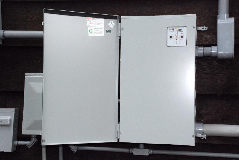
The ASCO automatic transfer switch shown with the weather door open, showing the dead front panel. The control panel for the ATS can be seen in the upper right of the picture. The conduit visible at the lower right of the ATS carries the feed from the 200 Amp main breaker to the ATS. The conduit coming from the upper right of the ATS now feeds the electric furnace circuit breakers. The small conduit visible below the ATS cabinet carries control wires.
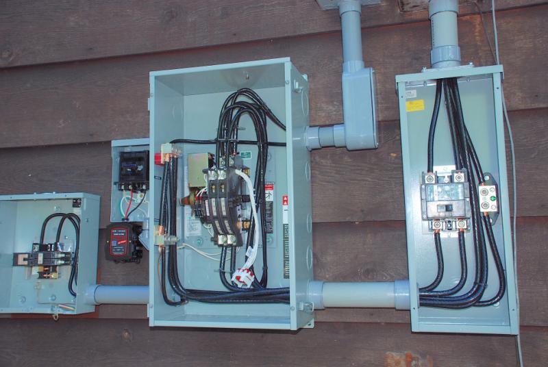
A view of the panels when they were partially wired. Here, the control electronics have been removed from the ATS for ease in connecting things.
The cabinet on the far left is used to select between either the 27 KW or the 5 KW gensets, Both the control circuits to the gensets and the AC power from the gensets are switched in this cabinet. Between this control cabinet and the ATS is mounted a small black box, which is a Transient Voltage Surge Suppressor (TVSS). This is connected directly across the incoming utility power line. Directly above the TVSS is a 2-pole fuse assembly to protect the TVSS and its wiring from vaporizing should the TVSS fail shorted.

The TVSS and its fuse box.
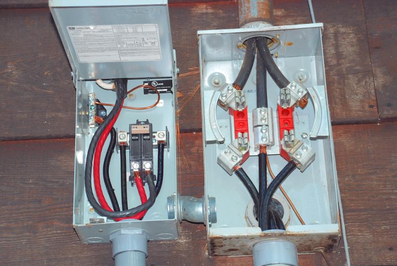
The meter panel and the electric furnace circuit breakers. Note the old unused conduit jumper between the two cabinets.

This is looking inside the ATS after everything has been wired up and functioning properly. (Yay!)
The control panel is in the upper right. The green plug connects to a rotary switch in the genset selector cabinet where the in-use genset is selected. The panel controls the engine start and stop, and operates the electric fuel valve.
The orange plug with the white wires connects the guts of the ATS to the ATS control panel. A terminal strip has been screwed to the back of the cabinet over the manufacturers obligatory safety warning label. The terminal strip is for various control wires that go inside the house and connect to a small monitor and control panel for the gensets and ATS.
A white Radio Shack wall-wart is tie-wrapped to the power cables in the lower left of the cabinet. It is used to monitor the utility power feed.
The actual transfer switch is visible just to the center left of the panel. Directly above the main ATS switch is a pair of black wire adapters for feeding the house loads from the output of the ATS.
The utility power feed comes in at the bottom of the switch assembly. At the top of the switch are two pairs of terminals. The front set are connected to the output of the generator(s), and the rear set are the output from the transfer switch.

As it turned out, I had to install a time delay relay system in the engine cranking circuit to get the genset to start properly. It seems as though the transfer panel control logic is too "quick on the trigger" and as soon as it sees the alternator start to produce and AC voltage, it decides the engine is already running and shuts of the engine start signal. Of course, the engine is not actually up to speed, so it comes to a stop, whereupon the control logic does a restart, with the same result. After three attempts to start the engine, and three failures, the control panel locks out the start circuit. Then I have to open the transfer panel and press the reset button and manually start the engine. This is not good.
The delay relays keep the engine starter engaged for four seconds, no matter what happens. This is enough to ensure the engine starts normally, even if the transfer panel control logic terminates the start signal prematurely. Should the engine not start within four seconds, the transfer panel logic will keep the starter engaged for a maximum of ten seconds. If the engine has not started by that time, something's wrong!

If you're an electrician, you'll cringe at this one! The wall-wart is connected between neutral and the utility line with a pair of Radio Shack clip leads. Chances are the wall-wart will never fail shorted. But if it does, you can be sure those famous RS 5 Amp clip leads will vaporize instantly! (So much for fuses.)

The gray cable from the right of the terminal strip goes into the house for control and monitoring of the genset and the ATS.

The wires from the plug on the ATS control panel that control the gensets.

The white wires connect the ATS switch to the ATS control panel. Note the small black relay that's tie-wrapped to the wires. It is controlled from inside the house and is used to prevent either of the gensets from being started by the ATS control panel. This is used for genset or ATS service or if we are away from the house for an extended length of time and do not want the genset to run in the case of a power failure.

There's a whole lotta' grounding goin' on!
In the local utility's scheme of things, the neutral and earth connections are bonded together. I had lots of connections to make to neutral/earth, so both blocks were strapped together as you see here.

Since our plans call for a second building for Bonnie's art studio and my ham shack, I wanted to be able to feed it from the existing power system. That meant that I had to be able to route the output of the ATS in three directions at once. I have to feed the original house load panel (200 A), the electric furnace feed (80 A) and the new building feed (125A). Since it was impossible to stuff all those wires into the ATS terminals, it was necessary to use a couple of very handy adapters to do the trick.
I needed two connectors that would handle four 2/0 wires on each connector. I found some (actually just one - this is a small town) sold by Polaris, but it was made to handle eight wires. I needed two that would handle four wires each. Hmm... Let's see - eight divided by 2 equals four, so... off to the bandsaw. Ten minutes later, I had the two connectors I needed. Some liquid PVC insulation was applied to the cut ends and allowed to dry for a few days. Just like factory made!
You can see the connectors mounted just above the output connections L3 and L7 of the ATS.

The control panel for the ATS. Pretty simple, huh? Well, yes, but... like all good computer logic, it can get into a snit and get really screwed up. It does not like electrical noise on the control lines, and it is happier with a back up battery instead of getting power from the genset battery. But, when it works, it works really well. I just wish some of the operating parameters were adjustable, but everything's burned into the PROM inside the control chip.

This is the conduit that carries the control and data lines from the ATS to the house and the genset control switchbox. I tried to keep control lines away from AC power lines as much as possible.
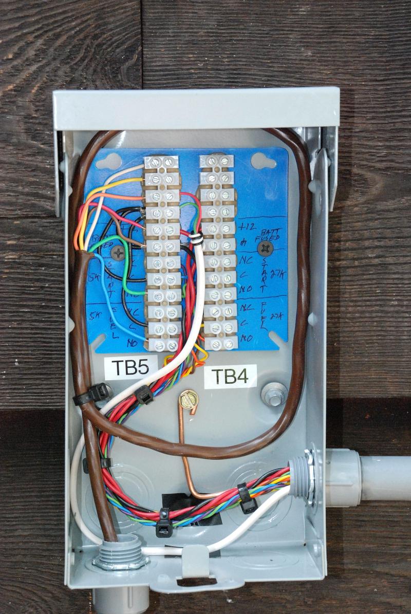
I took a small fusebox and removed the guts to obtain a weather tight empty box in which to place a pair of terminal strips for the genset control connections. It was cheaper to buy the fuse box and gut it than to buy a plain empty box. Go figure!
The brown cable running to TB5 comes from the 5 KW Onan genset. A similar cable from the 27 KW genset will connect to the right side terminal strip TB4.
The twisted multi-colored wires go to the next cabinet to the right of this one. That cabinet houses the AC circuit breakers and the rotary switch that transfers the actual engine control signals from the ATS control panel to the selected genset.
See the white cable? It runs up to the attic where it controls a small relay that shuts down the house 5 ton air conditioning compressor when the 5 KW genset is running. This necessary since the little 5 KW genset cannot handle the A/C system. The 27 KW genset will run everything, of course, so the relay is not used when the 27 KW genset is on line.
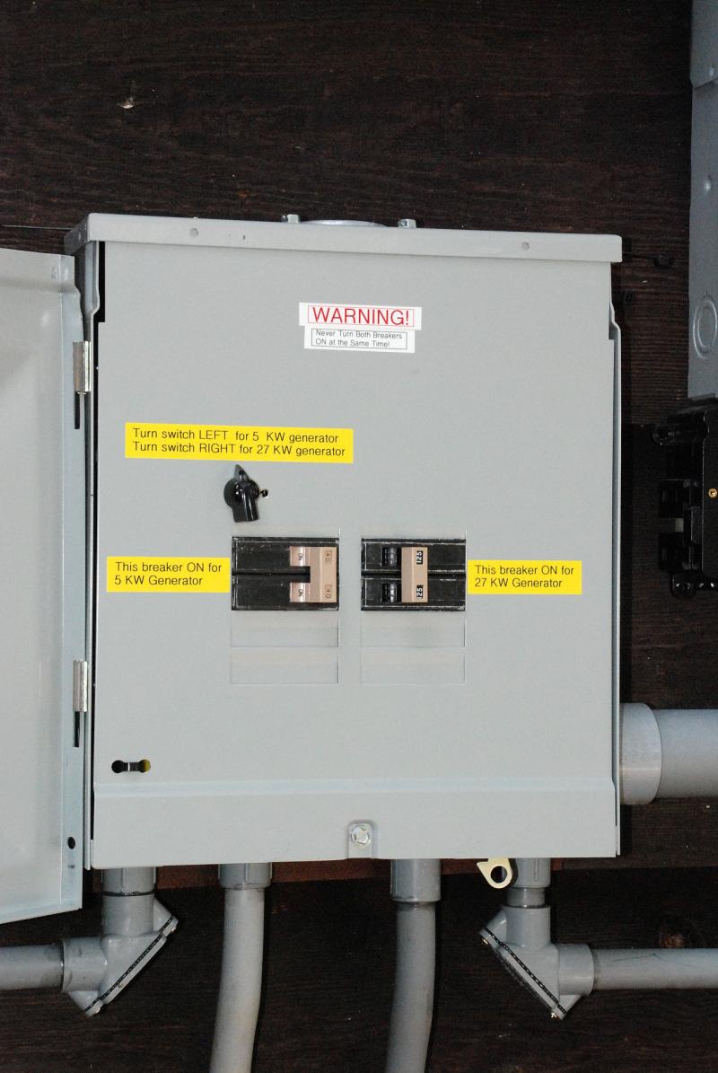
This cabinet houses a pair of circuit breakers. They are fed "in reverse" so that power from both gensets flows through the appropriate breaker and onto the buss back to the emergency power input terminals of the ATS. Needless to say, both breakers should never be turned on when either genset is running or the Magic Smoke will surely escape from one of the generators! This cabinet will be locked and only opened by Bonnie or I when it is necessary to transfer from one genset to the other.
Besides "throwing over" the AC power breakers when changing gensets, it is necessary to transfer the control lines as well. The "chicken head knob" rotary switch accomplishes that task.

Looking behind the panel during construction, you can see the rotary switch used to transfer the control lines between the two generators. The rotary switch terminates on TB3 which is mounted on the rear of the dead front panel. The coiled up wires were threaded through the small conduit and go back to the ATS cabinet on the green plug on the control panel, and also go to TB4 and TB5 to connect to the gensets.

Looking into the Generator Control Panel cabinet with the front cover in the maintenance position.
Note that the circuit breakers are in the 5 KW GENSET position. The AC feed wires from the 27 KW genset have not yet been run into the cabinet for connection to the breakers on the right side of the cabinet. The two wall-wart transformers in the bottom of the cabinet are for monitoring the AC power output of the two generators.
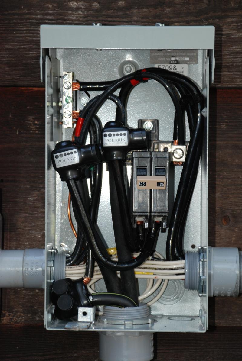
The wires going into the lower conduit are for the underground feeder running to the new ham shack/art studio we are constructing. This is the 125 Ampere main breaker for that feeder.
The white wires are connected to a reactance compensating capacitor that is connected across the utility power feed.

One of the "fun" things about living in the country is that you really get to play with your generator and electrical systems a whole lot!
One of the more annoying happenings is that we have had a great number of minor power bumps, burps and bobbles that greatly upset some of the in house electronics, including crashing several of the UPS units from time to time. Although the main power line on the road seems to hold up pretty well for voltage stability, I noticed that every time a motor driven appliance started up - especially the central A/C - the lights would dim a bit.
I did some checking, and I suspect that the power transformer feeding the house does not have a high surge current capability. I suspected that the inductive reactance of the motors was causing a high reactive current to flow, causing the voltage drop. Temporarily connecting a big capacitor across the line seemed to help, so back to the Junque Box I went. I found a big power factor correction capacitor, rated at 5 KVAR @ 240 volts. That should do the trick!
I mounted it up high on the outside wall where no one can get at it (The terminals were not covered with insulation when this picture was taken) and connected it through appropriate fuses back to the incoming feed from the local utility. Since the capacitor went on line, the incidence of power line disturbances has decreased to almost zero. The only light dimming I now see is when the main A/C cranks up, but it is greatly reduced from what I observed before.

Finally! All complete, after a lot of time, effort and money. But, the results are worth it. Everything is automatic and switches to the genset within 35 seconds after a power failure.

The control and monitor cable from the ATS comes into the house through the wall and terminates at terminal strip TB1. Also mounted on the wall is a 12 volt "D" cell battery pack that serves as the backup battery for the ASCO ATS. As long as power is supplied by either the local utility or the selected generator, the battery sees no current drain. Should the utility power go away and neither genset start, the battery will have to supply a 20 mA load. It will last about a week under that current drain.
The battery is needed because the design of the ATS control is such that in the event of a utility power failure, it will attempt to start the selected genset three times over a 30 second period. If the genset fails to start, the control panel will lock out the fuel supply and ignition system on the genset and then "go to sleep" until you manually reset the control panel. If no external battery is present, the control panel simply "dies" and will not start the genset even if you reset the panel.
One thing this panel really needs is a remote control connection that will allow you to see the status lamps and press the control panel reset button remotely. Due to the construction of the key panel (membrane keys and plastic strip wiring) it is difficult to kludge on external connections. Not to mention that: a) the unit is still under warranty, and, b) the panel costs $385.00 to replace if I screw it up.
.jpg)
I mounted a small control and expanded scale AC voltmeter on the wall inside the house.
The red lights tell me that 12 volts DC control power is available from both genset batteries, and that there is 12 volts available to trigger the emergency genset shutdown relay. The shutdown relay is controlled by the guarded toggle switch under the red cover.
The green lights are AC power samples generated by the Radio Shack wall-wart transformers. These LED's indicate that there is AC power available from the local utility or the generators.
The dark green square push button switch is used to initiate a genset load test or to lock the house onto the genset is needed during a poor utility power situation.
The expanded scale voltmeter lets me monitor the AC power coming from the local power company, or either of the two emergency generators
Now that the generators were installed, it was necessary to have a reliable fuel supply on hand for them. Because storing large quantities of gasoline or Diesel fuel would be difficult, and there are no natural gas lines in the area, it was necessary to use propane as the fuel source. Propane is ideal, as it stores indefinitely with no degradation or aging problems. Internal combustion engines like propane, and give very little trouble when using it as a fuel.

Since there was no possible way the gas line in the house would be able to supply the quantity of fuel needed to operate the engine in the genset, I decided to install a brand new underground gas line between the propane tanks and the generator. This was done while the trenches for the water lines and electric feeder were being dug. This view shows the service riser curving out of the ground by the genset. It is connected to the yellow pipe you can see partially buried in the trench.

Around the side of the house goes the new gas line.

It continues around the back of the house.

Towards the propane tanks.

Until it finally connects to the tanks.
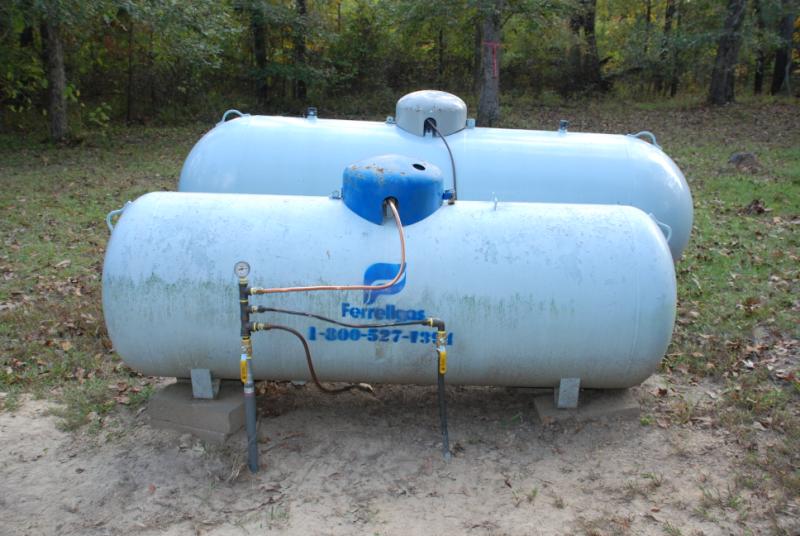
A manifold system allows either or both tanks to feed both the underground gas lines. The line on the right side goes to the gas service in the house, and the line on the left goes to the generator. There is a shut off valve on each line, and a shut off valve on each tank. Each tank has a separate 10 PSI regulator feeding the manifold. There is a pressure gauge on the manifold to tell me things are working correctly. The tank regulators are set so that the small tank will be used first, then fuel from the larger tank. There is a 10 PSI to 13" WC regulator at the house, and another at the genset.
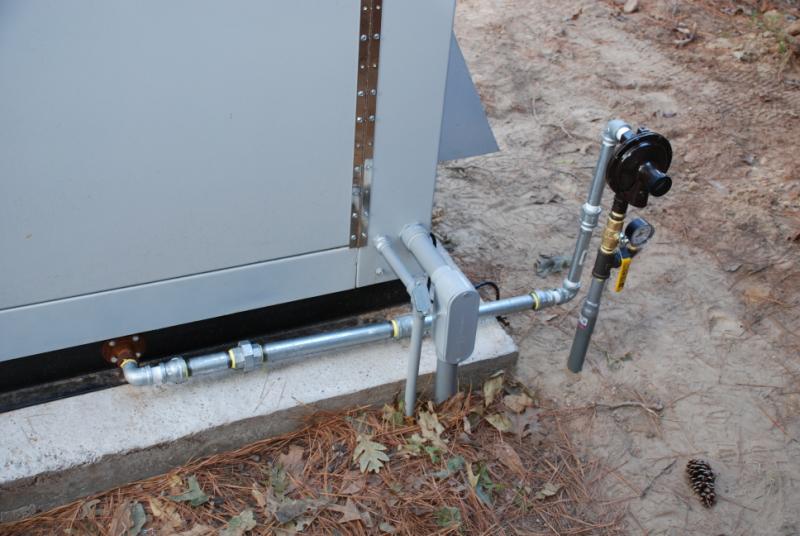
This is the regulator and pressure gauge at the generator end of the gas line. Note the numerous parts and pieces of pipe used between the regulator and the genset fuel fitting. this is what happens when you live in a small town and the hardware stores pipe threading machine is broken. You ":make do" what what you can find on the shelf!
73, Ralph W5JGV
[Home]
The entire contents of this web site are Copyright © 2002 - 2007 by Ralph M. Hartwell II, all rights reserved.