
Another WC2XSR/13 Antenna Insulator Failure!
by W5JGV
February 20,2005
The key to successful operation of a radio transmission system is to keep all the smoke inside the various system components. WC2XSR/13 was doing pretty good in that department, until late on the evening of January 14, 2005. At about 2200 hours local time, the lower feed bar PVC plastic standoff insulator that holds the feed bar away from the antenna tower began to fail by arc tracking and thermal decomposition (it burned up). The insulator failure was discovered the next morning at about 0435 local time when I observed that the transmitters PA stage drain current had fallen to about 25% of normal. Attempts to retune the antenna using the remote tuning motor were unsuccessful. The VSWR remained very low, but the forward power was only about 100 watts. A visual inspection of the antenna system revealed what you see in the picture below!
There's a hot time on the old tower tonight!
It's 0430 on a foggy Louisiana morning, and the acrid smoke from the burning insulator gently drifts into the swirling fog.
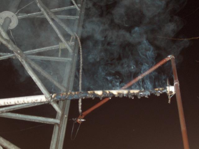
A closer view of the damage shows that the insulator failed across its entire length, finally forming a conducting path between the grounded antenna tower and the vertical copper feed pipe. Note the short section of plastic rope hanging uselessly from the right side of the tower. The rope was used to keep tension on the outer end of the thin-walled PVC support pipe.

This side view shows the smoke from the burning insulator drifting off to the right into the early morning fog. This is very acrid and dangerous smoke, containing Chlorine compounds and Hydrochloric Acid gas. It can cause severe lung damage if it is inhaled.

Daylight reveals the full scope of the destruction. Most of the bottom portion of the insulating pipe is missing. It was converted into smoke and fine black ash which now coats the top of the antenna tuning cabinet. I washed the ash off immediately, as it causes severe corrosion very quickly if left on metal surfaces.

In this picture you can see that the RF current went to ground where the PVC pipe first contacted the grounded antenna tower. The PVC pipe was held to the tower by several wraps of #12 insulated copper wire. The wire and its insulation was undamaged, except for a slight amount of heat damage from the burning PVC pipe.

You can see the instant corrosion produced by the decomposition products in the smoke from the burning PVC pipe. Note the yellow colored bolt and nut holding the anti-corona ring in place. That is stainless steel hardware! The smoke has permanently stained the metal. And yes, the green corrosion on the pipe and anti-corona ring is thick enough to scrape off in chunks with your fingernail.

This is an overall view of the antenna fed system after repairs had been completed. A new insulator is in place, This one is a used ships antenna insulator, and shows ample evidence of having been used in a salt atmosphere. It is still quite serviceable for this frequency and RF power level.

This view of the new insulator shows that left (cold for RF) end of the insulator is jammed into a length of 2 inch diameter PVC pipe. In order to hold the insulator in place in the pipe, a 1/4 inch diameter bolt is passed crosswise through the pipe and through the eye of the metal end bell of the insulator. Tightening the bolt squeezes the PVC against the metal end bell and firmly clamps the insulator in place so it cannot move. The right hand end bell has an "L" bracket attached to it which holds the vertical antenna feed pipe in position. The "L" bracket was needed because the position of the PVC pipe holding the insulator was determined by the "X" braces in the tower legs. Note the anti-corona ring is installed on the bolt attaching the far end of the "L" bracket to the vertical feed pipe. Since the bolt sticks out from the feed pipe and the end of the bolt presents a fairly sharp point, the anti-corona ring was needed to prevent corona from forming on the end of the bolt.

Looking down at the new insulator assembly you can see the metal screw (hose) clamps that hold the PVC pipe firmly against the tower leg braces.

A view of the hot end of the insulator assembly.

The cold end of the insulator. The ceramic rod of the new insulator is about 1.125 inches thick and about 14 inches long. Hopefully this will not allow the RF to track across it and damage the surface as it did to the PVC pipe. Notice the gray antenna tuning cabinet below the insulator assembly. On top of the cabinet is an inverted red plastic bucket which covers the motor drive for the variometer. I needed a way to keep the bucket in place so wind would not blow it off during storms. I also needed a way to keep my "RF Monitor Bottle" in place. The RF Monitor Bottle is the empty 2 liter soda bottle with a small fluorescent lamp inside it that is seen on top of the bucket. It lights up when the transmitter is on so I can have a visual monitor at night as well as a warning that the antenna system is "hot" when I am working near the tuner. I solved both problems by "recycling" a dead gel-cell battery. I cemented the RF Monitor Bottle to the battery and placed the bottle and battery on top of the bucket. Everything stays in place and is easy to remove as needed.

A top view showing the relative placement of the insulator, "L" bracket and feed pipe.

The cold end of the insulator must be grounded, so I installed a length of #10 wire between the end bell clamp bolt and the tower leg. Leaving this end of the insulator ungrounded would result in a high RF field being set up between the tower and the ungrounded cold end bell, which could cause RF tracking and burn the PVC pipe between the tower and the end bell.

This is a graph of the final RF PA stage drain current (top graph) and voltage (bottom graph) over the period of the Big Burnout. The time period shown here is almost 5 hours.

An expanded view of the start of the insulator failure. Note that the first "R" in "XSR" is starting to show a drop off during the last 60 seconds of the dash. Things go downhill rather rapidly from that point until I shut down the transmitter. The drain current was indicating about 9 amperes, when it normally reads closer to 20 amperes.

End of the burnout. You can see that I locked the transmitter carrier on as I tried to tune the antenna, and finally gave up about 240 seconds later, after I went outside and discovered the damage. Both the drain voltage and current dropped to zero when I shut down the transmitter.
73, Ralph W5JGV
[Home]
The entire contents of this web site are Copyright © 2002 by Ralph M. Hartwell II, all rights reserved.