A Seven Pole 500 KHz High Pass Filter Using Available Parts
by W5JGV
Revised - March 22, 2009
Authors Note: Although this project was actually completed in January 2004, I never placed this information about it on my web site until now for several reasons. First, I managed to lose the paperwork with all the component values, (!) and second, Hurricane Katrina came along and brought most everything to a halt. Now, however, I am trying to being things up to date, so I'm posting this project even without the component values. I'll add them to this web page a soon as I find that data somewhere in my files, which are in a state of complete disarray. So, right now, this article is primarily a "construction idea" piece.
This article describes a shielded high pass filter with a cut off frequency of about 500 KHz. It is built with components suitable for receiving, and was designed to use in front of a low frequency receiver for LOWFER work. As designed, the attenuation curve reduced the signal from my 166.5 KX experimental transmitter very effectively.
The filter was constructed from salvaged parts. The silver mica capacitors were salvaged from a variety of scrapped television receivers and computer monitors. The three toroidal inductors were made from cores salvaged from defunct computer power supplies, and the wire for the inductors came from wire salvaged from the TV receivers.
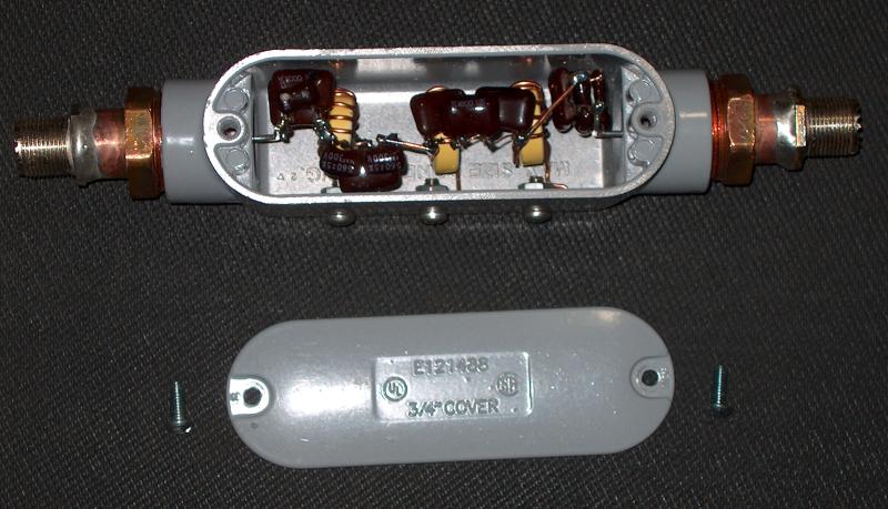
The enclosure was fabricated from a cast aluminum electrical junction "pull" box. I found that a copper pipe to iron pipe adapter would screw into the threaded openings of the pull box and an SO-239 connector could be soldered into the other end of the copper adapter. After the cover was screwed in place, the filter turned out to be quite well shielded.
The high pass filter is constructed inside of a 3/4" electrical "pull" box. SO-239 female connectors are soldered to Copper to Iron pipe adapters. The adapters are screwed into the threaded openings of the pull box. When the cover is in place, the filter is well shielded.

Three screws are used to connect the low side of the three inductor filter poles to the earth/ground side of the filter unit.

The open edges of the pull box and the mating edges of the cover have had all paint removed so that when they are fastened together they will make good electrical contact and make the shielding more effective.

There are three inductance poles and four capacitance poles in this filter. The inductors were wound to the nearest whole turn to obtain an approximation of the required value, and the capacitors were built up by using series-parallel combinations of capacitors to obtain the required values. Even though the inductances were not quite exactly as calculated, the performance of the filter was quite satisfactory.
Because toroidal inductors are inherently self-shielding, they may be placed inside of rather small enclosures without incurring more than minimal losses. Note that placing the windings too close to the walls of the enclosure or other components can cause the stray capacity to increase sufficiently to cause detuning or unwanted coupling between filter sections.
73, Ralph W5JGV
[Home]
The entire contents of this web site are Copyright © 2002 - 2009 by Ralph M. Hartwell II, all rights reserved.